


You also want an ePaper? Increase the reach of your titles
YUMPU automatically turns print PDFs into web optimized ePapers that Google loves.
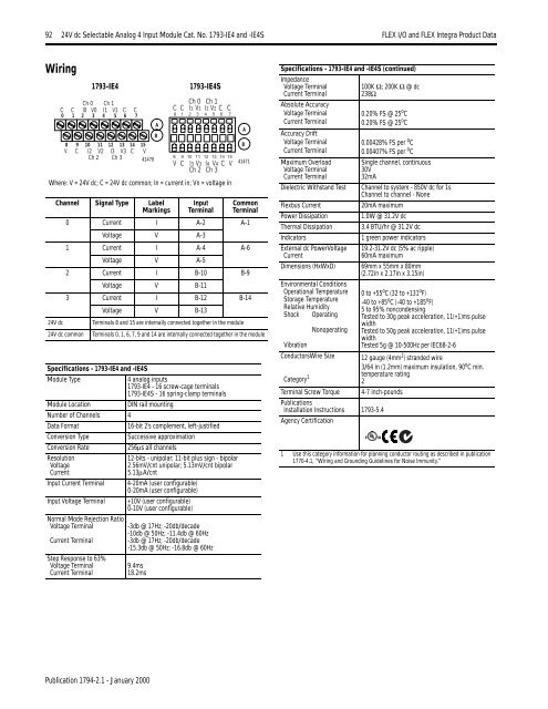
92 24V dc Selectable Analog 4 Input Module Cat. No. 1793-IE4 <strong>and</strong> -IE4S <strong>FLEX</strong> I/O <strong>and</strong> <strong>FLEX</strong> <strong>Integra</strong> Product DataWiringCh 0 Ch 1C C I0 V0 I1 V1 C C0 1 2 3 4 5 6 78 9 10 11 12 13 14 15BV C I2 V2 I3 V3 C VCh 2 Ch 38 9 10 11 12 13 14 1541470V C I3 V3 I4 V4 C VCh 2 Ch 341471Channel Signal Type LabelMarkingsInputTerminalCommonTerminal0 Current I A-2 A-1Voltage V A-31 Current I A-4 A-6Voltage V A-52 Current I B-10 B-9Voltage V B-113 Current I B-12 B-14Voltage V B-1324V dcTerminals 8 <strong>and</strong> 15 are internally connected together in the module24V dc common Terminals 0, 1, 6, 7, 9 <strong>and</strong> 14 are internally connected together in the moduleSpecifications - 1793-IE4 <strong>and</strong> -IE4SModule Type4 analog inputs1793-IE4 - 16 screw-cage terminals1793-IE4S - 16 spring-clamp terminalsModule LocationDIN rail mountingNumber of Channels 4Data Format16-bit 2’s complement, left-justifiedConversion TypeSuccessive approximationConversion Rate256µs all channelsResolutionVoltageCurrentInput Current TerminalInput Voltage TerminalNormal Mode Rejection RatioVoltage TerminalCurrent Terminal1793-IE4Step Response to 63%Voltage TerminalCurrent Terminal12-bits - unipolar; 11-bit plus sign - bipolar2.56mV/cnt unipolar; 5.13mV/cnt bipolar5.13µA/cnt4-20mA (user configurable)0-20mA (user configurable)+10V (user configurable)0-10V (user configurable)-3db @ 17Hz; -20db/decade-10db @ 50Hz; -11.4db @ 60Hz-3db @ 17Hz; -20db/decade-15.3db @ 50Hz; -16.8db @ 60Hz9.4ms18.2msABC C1793-IE4SCh 0 Ch 1CCI1 V1 I2 V20 1 2 3 4 5 6 7Where: V = 24V dc; C = 24V dc common; In = current in; Vn = voltage inASpecifications - 1793-IE4 <strong>and</strong> -IE4S (continued)ImpedanceVoltage TerminalCurrent TerminalAbsolute AccuracyVoltage TerminalCurrent TerminalAccuracy DriftVoltage TerminalCurrent TerminalMaximum OverloadVoltage TerminalCurrent TerminalDielectric Withst<strong>and</strong> TestFlexbus CurrentPower DissipationThermal DissipationIndicatorsExternal dc PowerVoltageCurrentDimensions (HxWxD)Environmental ConditionsOperational TemperatureStorage TemperatureRelative HumidityShock OperatingNonoperatingVibrationConductorsWire SizeCategory 1Terminal Screw Torque100K Ω; 200K Ω @ dc238Ω0.20% FS @ 25 o C0.20% FS @ 25 o C0.00428% FS per o C0.00407% FS per o CPublicationsInstallation Instructions 1793-5.4Agency CertificationSingle channel, continuous30V32mAChannel to system - 850V dc for 1sChannel to channel - None20mA maximum1.0W @ 31.2V dc3.4 BTU/hr @ 31.2V dc1 green power indicators19.2-31.2V dc (5% ac ripple)60mA maximum69mm x 55mm x 80mm(2.72in x 2.17in x 3.15in)0 to +55 o C (32 to +131 o F)-40 to +85 o C (-40 to +185 o F)5 to 95% noncondensingTested to 30g peak acceleration, 11(+1)ms pulsewidthTested to 50g peak acceleration, 11(+1)ms pulsewidthTested 5g @ 10-500Hz per IEC68-2-612 gauge (4mm 2 ) str<strong>and</strong>ed wire3/64 in (1.2mm) maximum insulation, 90 o C min.temperature rating24-7 inch-pounds1 Use this category information for planning conductor routing as described in publication1770-4.1, “Wiring <strong>and</strong> Grounding Guidelines for Noise Immunity.”Publication 1794-2.1 - January 2000


