


You also want an ePaper? Increase the reach of your titles
YUMPU automatically turns print PDFs into web optimized ePapers that Google loves.
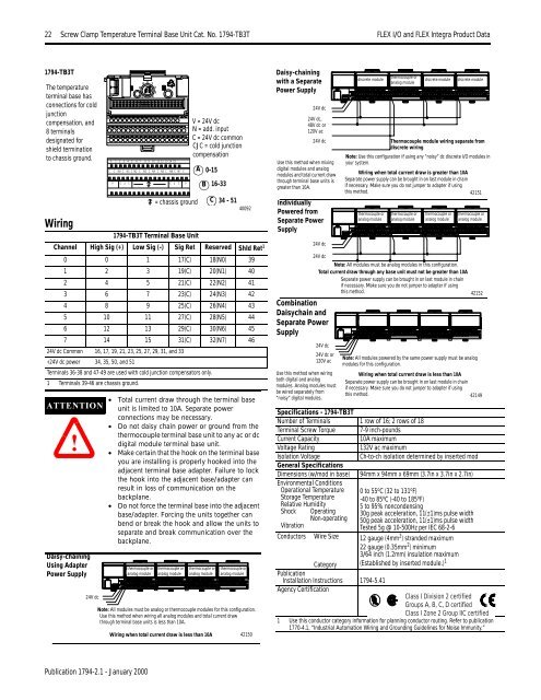
22 Screw Clamp Temperature Terminal Base Unit Cat. No. 1794-TB3T <strong>FLEX</strong> I/O <strong>and</strong> <strong>FLEX</strong> <strong>Integra</strong> Product DataScrew Clamp Temperature Terminal Base Unit Cat. No. 1794-TB3T1794-TB3TThe temperatureterminal base hasconnections for coldjunctioncompensation, <strong>and</strong>8 terminalsdesignated forshield terminationto chassis ground.Wiring1794-TB3T Terminal Base UnitChannel High Sig (+) Low Sig (-) Sig Ret Reserved Shld Ret 10 0 1 17(C) 18(N0) 391 2 3 19(C) 20(N1) 402 4 5 21(C) 22(N2) 413 6 7 23(C) 24(N3) 424 8 9 25(C) 26(N4) 435 10 11 27(C) 28(N5) 446 12 13 29(C) 30(N6) 457 14 15 31(C) 32(N7) 4624V dc Common 16, 17, 19, 21, 23, 25, 27, 29, 31, <strong>and</strong> 33+24V dc power 34, 35, 50, <strong>and</strong> 51Terminals 36-38 <strong>and</strong> 47-49 are used with cold junction compensators only.1 Terminals 39-46 are chassis ground.ATTENTION!Daisy-chainingUsing AdapterPower Supply24V dcC0 1 2 3 4 5 6 7 8 9 10 11 12 13 14 15C N0 C N1 C N2 C N3 C N4 C N5 C N6 C N7 CV C J C C J C V= chassis groundV = 24V dcN = add. inputC = 24V dc commonCJC = cold junctioncompensation0-1516-33• Total current draw through the terminal baseunit is limited to 10A. Separate powerconnections may be necessary.• Do not daisy chain power or ground from thethermocouple terminal base unit to any ac or dcdigital module terminal base unit.• Make certain that the hook on the terminal baseyou are installing is properly hooked into theadjacent terminal base adapter. Failure to lockthe hook into the adjacent base/adapter canresult in loss of communication on thebackplane.• Do not force the terminal base into the adjacentbase/adapter. Forcing the units together canbend or break the hook <strong>and</strong> allow the units toseparate <strong>and</strong> break communication over thebackplane.thermocouple oranalog modulethermocouple oranalog moduleABthermocouple oranalog moduleC 34 - 5140092Note: All modules must be analog or thermocouple modules for this configuration.Use this method when wiring all analog modules <strong>and</strong> total current drawthrough terminal base units is less than 10A.Wiring when total current draw is less than 10Athermocouple oranalog module42150Daisy-chainingwith a SeparatePower SupplySpecifications - 1794-TB3TNumber of Terminals 1 row of 16; 2 rows of 18Terminal Screw Torque 7-9 inch-poundsCurrent Capacity10A maximumVoltage Rating132V ac maximumIsolation VoltageCh-to-ch isolation determined by inserted modGeneral SpecificationsDimensions (w/mod in base) 94mm x 94mm x 69mm (3.7in x 3.7in x 2.7in)Environmental ConditionsOperational TemperatureStorage TemperatureRelative HumidityShockVibrationConductors24V dc24V dc,48V dc or120V ac24V dcUse this method when mixingdigital modules <strong>and</strong> analogmodules <strong>and</strong> total current drawthrough terminal base units isgreater than 10A.IndividuallyPowered fromSeparate PowerSupply24V dcCombinationDaisychain <strong>and</strong>Separate PowerSupplyOperatingNon-operatingWire Sizediscrete moduleCategoryPublicationInstallation Instructions 1794-5.41Agency Certificationthermocouple oranalog modulediscrete moduleThermocouple module wiring separate fromdiscrete wiringNote: Use this configuration if using any “noisy” dc discrete I/O modules inyour system.Wiring when total current draw is greater than 10ASeparate power supply can be brought in on last module in chainif necessary. Make sure you do not jumper to adapter if usingthis method.42151thermocouple oranalog modulethermocouple oranalog modulethermocouple oranalog module0 to 55 o C (32 to 131 o F)-40 to 85 o C (-40 to 185 o F)5 to 95% noncondensing30g peak acceleration, 11(±1)ms pulse width50g peak acceleration, 11(±1)ms pulse widthTested 5g @ 10-500Hz per IEC 68-2-612 gauge (4mm 2 ) str<strong>and</strong>ed maximum22 gauge (0.35mm 2 ) minimum3/64 inch (1.2mm) insulation maximum(Established by inserted module.) 1discrete modulethermocouple oranalog module24V dcNote: All modules must be analog modules in this configuration.Total current draw through any base unit must not be greater than 10ASeparate power supply can be brought in on last module in chainif necessary. Make sure you do not jumper to adapter if usingthis method.4215224V dc24V dc or120V acUse this method when wiringboth digital <strong>and</strong> analogmodules. Analog modules mustbe wired separately from“noisy” digital modules.Note: All modules powered by the same power supply must be analogmodules for this configuration.Wiring when total current draw is less than 10ASeparate power supply can be brought in on last module in chainif necessary. Make sure you do not jumper to adapter if usingthis method.42149Class I Division 2 certifiedGroups A, B, C, D certifiedClass I Zone 2 Group IIC certified1 Use this conductor category information for planning conductor routing. Refer to publication1770-4.1, “Industrial Automation Wiring <strong>and</strong> Grounding Guidelines for Noise Immunity.”Publication 1794-2.1 - January 2000


