


You also want an ePaper? Increase the reach of your titles
YUMPU automatically turns print PDFs into web optimized ePapers that Google loves.
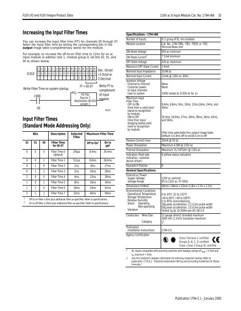
<strong>FLEX</strong> I/O <strong>and</strong> <strong>FLEX</strong> <strong>Integra</strong> Product Data 120V ac 8 Input Module Cat. No. 1794-IA8 33120V ac 8 Input Module Cat. No. 1794-IA8Increasing the Input Filter TimesYou can increase the input filter time (FT) for channels 00 through 07.Select the input filter time by setting the corresponding bits in theoutput image table (complementary word) for the module.For example, to increase the off-to-on filter time to 12ms for an acinput module at address rack 1, module group 0, set bits 02, 01, <strong>and</strong>00 as shown below.O:01015 14 13 12 11 10 09 08 07 06 05 04 03 02 01 0017 16 15 14 13 12 11 10 07 06 05 04 03 02 01 001 0 0 1 0 0Write Filter Time on system startup.I:00000Input Filter Times(St<strong>and</strong>ard Mode Addressing Only)Bits Description SelectedFilter02 01 00 Filter Timefor 00-07FT = 00-07FLLFill FileSource 3Destination #0:010Length 1Maximum Filter TimeOff to On 1Dec. (Octal)=3 Octal or3 DecimalWrite FT tocomplementof inputmodule.40103On toOff 20 0 0 Filter Time 0 256µs 8.4ms 26.4ms(default)0 0 1 Filter Time 1 512µs 8.6ms 26.6ms0 1 0 Filter Time 2 1ms 9ms 27ms0 1 1 Filter Time 3 2ms 10ms 28ms1 0 0 Filter Time 4 4ms 12ms 30ms1 0 1 Filter Time 5 8ms 16ms 34ms1 1 0 Filter Time 6 16ms 24ms 42ms1 1 1 Filter Time 7 32ms 40ms 58ms1 Off to on filter is 8ms plus additional filter as specified. Refer to specifications.2 On to off filter is 26ms plus additional filter as specified. Refer to specifications.Specifications - 1794-IA8Number of InputsModule LocationON-State VoltageON-State Current 1OFF-State VoltageMaximum OFF-State CurrentNominal Input ImpedanceNominal Input CurrentIsolation VoltageChannel to channelCustomer powerto input channelsUser to systemMaximum InputFilter TimeOFF to ON(time from a valid inputsignal to recognitionby module)ON to OFF(time from inputdropping below validlevel to recognitionby module)Flexbus Current (max)Power DissipationThermal DissipationIndicators (field sideindication, customerdevice driven)Keyswitch Position 8General SpecificationsExternal ac PowerSupply VoltageVoltage RangeDimensions HxWxDEnvironmental ConditionsOperational TemperatureStorage TemperatureRelative HumidityShockOperatingNon-operatingVibrationConductors Wire SizeCategory8 (1 group of 8), non-isolatedCat. No. 1794-TBN, -TB3, -TB3S, or -TB2Terminal Base Unit65V ac minimum7.1mA minimum43V ac maximum2.9mA10.6K Ω12mA @ 120V ac, 60HzNoneNonePublicationInstallation Instructions 1794-5.9Agency Certification100% tested at 2150V dc for 1s8.4ms, 8.6ms, 9ms, 10ms, 12ms,16ms, 24ms, <strong>and</strong>40ms26.4ms, 26.6ms, 27ms, 28ms, 30ms, 34ms, 42ms,<strong>and</strong> 58msFilter time selectable thru output image tableDefault is 8.4ms off to on/26.4 on to off30mA @ 5V dcMaximum 4.5W @ 132V acMaximum 15.3 BTU/hr @ 132V ac8 yellow status indicators120V ac nominal85 to 132V ac, 47-63Hz46mm x 94mm x 53mm (1.8in x 3.7in x 2.1in)0 to 55 o C (32 to 131 o F)-40 to 85 o C (-40 to 185 o F)5 to 95% noncondensing30g peak acceleration, 11(±1)ms pulse width50g peak acceleration, 11(±1)ms pulse widthTested 5g @ 10-500Hz per IEC 68-2-612 gauge (4mm2) str<strong>and</strong>ed maximum3/64 inch (1.2mm) insulation maximum1 2Class I Division 2 certifiedGroups A, B, C, D certifiedClass I Zone 2 Group IIC certified1 AC inputs compatible with proximity switches with leakage ratings of I leak < 2.5mA <strong>and</strong>I on maximum = 5mA.2 Use this conductor category information for planning conductor routing. Refer topublication 1770-4.1, “Industrial Automation Wiring <strong>and</strong> Grounding Guidelines for NoiseImmunity.”Publication 1794-2.1 - January 2000


