134 Choosing the Correct Counter Module for Your Application <strong>FLEX</strong> I/O <strong>and</strong> <strong>FLEX</strong> <strong>Integra</strong> Product DataChoosing the Correct Counter Module for Your Application1794-IJ21794-ID2Description: Essentially a tachometer with the capability of reportingfrequency, acceleration, <strong>and</strong> direction. Outputs are activated byalarms. Input devices range from magnetic pickup to flowmeters, toincremental encoders to proximity detectors.This intelligent I/O module is designed to perform high-speedfrequency algorithms. The module provides 2 frequency inputs, 2 gateinputs, <strong>and</strong> 2 outputs. The frequency inputs are capable of acceptingfrequencies up to 32KHz. The module accepts <strong>and</strong> returns binary data.The 1794-IJ2 measures frequency over a user-specified time interval. Afrequency calculation can start before the time interval has elapsed, ifa user-specified number of frequency input pulses have occurred.The module’s primary target is high-speed, accurate frequencymeasurement. As such, a high-speed internal clock is synchronizedwith the frequency input to count over a user-selected sampling timeor a user-defined number of frequency input pulses. All power forinput devices (24V dc) is supplied by the I/O module.Applications: Any application requiring rotational control includingturbine generators, motors, drives, gears, shafts, etc.Description: A counter module with 2 incremental quadratureencoder interfaces, each with four inputs (A, B, Z, <strong>and</strong> G).Each input module has + inputs for connection to pulse transmitterswith complementary or non-complementary signals.The counter can count one or two pulse trains for up/down counting<strong>and</strong> detection of a selectable number of edges (X1, X2, X4). Each ofthe two counters has an upper limit of 100KHz, a 16-bit counterregister, a preset register, <strong>and</strong> a latch register.Power to the module is supplied from an external power supply.Applications: Typical applications include quantity counting,positioning, <strong>and</strong> speed calculations.Signal Types:Input = 12V to 24V square wave limited to 100KHzOutput = NoneNetwork Compatibility: All networks supported by <strong>FLEX</strong> I/OSignal Types:Input = 50mV, 500mV, 3V, 6V, 24V sine or square waveup to 32KHz Output = Two 24V dc digital source outputscurrent-limited to 1ANetwork Compatibility: All networks supported by <strong>FLEX</strong> I/O1794-VHSCDescription: A counter module with two incremental quadratureencoder interfaces, each with three inputs (A, B, <strong>and</strong> Z). Each inputmodule as + inputs for connection to pulse transmitters withcomplementary or non-complementary signals.The counter can count one or two pulse trains for up/down counting<strong>and</strong> detection of a selectable number of edges (X1, X2, X4). Each ofthe two counters has an upper limit of 1MHz, a 24-bit counter register,a preset register, <strong>and</strong> a latch register.Power to the module is supplied from an external power supply.Outputs can be configured for overlapping, multiple windows, <strong>and</strong>/orpulse with modulation.Applications: Typical applications include packaging, materialh<strong>and</strong>ling, flow monitoring, cut-to-length, motor speed control <strong>and</strong>monitoring.Signal Types:Input = 5V, 15V, or 24V dc square wave limited to 1MHzOutput = Four 5V or 12-24V dc digital source outputs,on-state current maximum 1A, maximum current peroutput pair is.5ANetwork Compatibility: Use with 1794-ACN(R)15 ControlNet only.1794-IP4Description: A counter module with 4 pulse transmitter interfaces(12-24V dc), each with two signal inputs (N <strong>and</strong> D).Each input module has + inputs for connection to pulse transmitters.Each interface may be configured for: a) period of time measurementusing one 16-bit counter <strong>and</strong> accumulating pulse counting using theother 16-bit counter or b) period time measurement using a 32-bitcounter.The number of periods to be measured is selectable (1, 2, 4, 8, 16, 32,64, <strong>and</strong> 128) via the gate control.Power to the module is supplied from an external power supply.Applications: Typical applications include counting pulses from flowmeters <strong>and</strong> density meters. Quantity counting <strong>and</strong> speed calculationsare examples of other applications.Signal Types:Input = 12V to 24V square wave limited to 100KHzOutput = NoneNetwork Compatibility: All networks supported by <strong>FLEX</strong> I/OPublication 1794-2.1 - January 2000
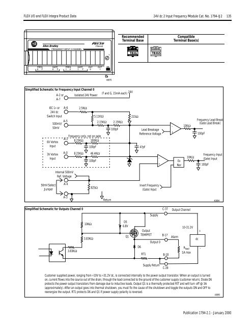
<strong>FLEX</strong> I/O <strong>and</strong> <strong>FLEX</strong> <strong>Integra</strong> Product Data 24V dc 2 Input Frequency Module Cat. No. 1794-IJ2 13524V dc 2 Input Frequency Module Cat. No. 1794-IJ2RecommendedTerminal BaseCompatibleTerminal Base(s)FREQUENCY INPUT 2 CHANNEL1794-IJ21TB3GTB3GSFREQ GATE FREQ GATE OUT OUT OK0 F 0 F 1 F 1 F 0 140870Simplified Schematic for Frequency Input Channel 0A-2 or Isolated 24V PowerA-7(F <strong>and</strong> G, 15mA each) 24VIEC 1+ or24V dcSwitch Input500mV/50mV6V VortexInputA-6A-52.5KΩ5.11KΩ2.15KΩFrequency only, not on gateA-18.25KΩ 100KΩ100pF2.15KΩ100pF215ΩLead BreakageReference Voltage47pF-+10KΩFrequency Lead Break(Gate Lead Break)100pF3V VortexInputA-08.25KΩ46.4KΩ100pF-+ExNor10KΩFrequency Input(Gate) Input100pFInternal 500mVRef. Voltage50mV SelectJumperA-4825ΩInvert Frequency(Gate) InputA-3Return40894Simplified Schematic for Outputs Channel 0SupplyC-37Output Channel3.83KΩ10KΩ3.83KΩD56.8VQ1D6OutputTEMPFETRT1Output 0B-17B-18Alarm10-31.2VR load1A maxdc+-Supply ReturnC-39Customer supplied power, ranging from +10V to +31.2V dc, is connected internally to the power output transistor. When an output is turnedon, current flows into the source out of the drain, through the load connected to the ground of the customer supply (customer return). Diode D6protects the power output transistors from damage due to inductive loads. Output Q1 is a thermally protected FET <strong>and</strong> will turn off @ 3A(approximately). After an output goes into thermal shutdown, you must fix the cause of the shutdown <strong>and</strong> toggle the outputs ON <strong>and</strong> OFF toreenergize the output. RT1 protects D6 <strong>and</strong> Q1 if power supply polarity is reversed.40895Publication 1794-2.1 - January 2000