


Create successful ePaper yourself
Turn your PDF publications into a flip-book with our unique Google optimized e-Paper software.
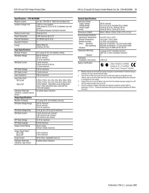
<strong>FLEX</strong> I/O <strong>and</strong> <strong>FLEX</strong> <strong>Integra</strong> Product Data 24V dc 10 Input/6 2A Output Combo Module Cat. No. 1794-IB10XOB6 85Specifications - 1794-IB10XOB6Module LocationCat. No. 1794-TB3 or -TB3S Terminal Base UnitIsolation Voltage (min) 1250V ac (rms) isolation100% tested at 2121V dc for 1s between user <strong>and</strong>systemNo isolation between individual channelsFlexbus Current (max) 35mA @ 5V dcPower Dissipation 6.0W maximum @ 31.2VThermal Dissipation 20.3 BTU/hr @ 31.2V dcKeyswitch Position 2Fusing 1SAN-O MQ4-3ALittelfuse 235 003Input SpecificationsNumber of Inputs10 (1 group of 10), non-isolated, sinkingON-State Voltage10V dc minimum;24V dc nominal;31.2V dc maximumON-State Current2.0mA minimum;8.0mA nominal at 24V dc;11.0mA maximumOFF-State Voltage5.0V dc maximumOFF-State Current1.5mA minimumInput Impedance4.8K Ω maximumInput Filter Time 2OFF to ONON to OFFIndicators (field sideindication, customer devicedriven)Output SpecificationsNumber of OutputsON-State Voltage RangeON-State Voltage DropON-State CurrentOFF-State VoltageOFF-State LeakageOutput Current RatingOutput Signal Delay 3OFF to ONON to OFFSurge CurrentIndicators (field sideindication, logic driven)0.25ms, 0.5ms, 1ms, 2ms, 4ms, 8ms, 16ms, 32ms0.25ms, 0.5ms, 1ms, 2ms, 4ms, 8ms, 16ms, 32ms0.25ms default - Selectable using configurationword 3. (Not selectable when used with the1794-ASB adapter.)10 yellow status indicators6 (1 group of 6), non-isolated, sourcing10V dc minimum;24V dc nominal;31.2V dc maximum1V dc @ 2A, 0.5V dc @ 1A maximum1.0mA minimum per channel;2.0A maximum per channel;10A maximum per module31.2V dc maximum0.5mA maximum2A per output,10A per module maximum0.5ms maximum1.0ms maximum4A for 50ms, repeatable every 2s6 yellow status indicatorsGeneral SpecificationsExternal dc PowerSupply VoltageVoltage RangeOutput SupplyCurrentDimensions HxWxDEnvironmental ConditionsOperational TemperatureStorage TemperatureRelative HumidityShock OperatingNon-operatingVibrationConductors Wire SizeCategoryPublicationInstallation Instructions 1794-5.24Agency Certification24V dc nominal19.2 to 31.2V dc (includes 5% ac ripple)15mA @ 19.2V dc; 19mA @ 24V dc24mA @ 30V dc; 25mA @ 31.2V dc46mm x 94mm x 53mm (1.8in x 3.7in x 2.1in)0 to 55 o C (32 to 131 o F)-40 to 85 o C (-40 to 185 o F)5 to 95% noncondensing30g peak acceleration, 11(±1)ms pulse width50g peak acceleration, 11(±1)ms pulse widthTested 5g @ 10-500Hz per IEC 68-2-612 gauge (4mm 2 ) str<strong>and</strong>ed maximum3/64 inch (1.2mm) insulation maximum2 4Class I Division 2 certifiedGroups A, B, C, D certifiedClass I Zone 2 Group IIC certified1 Module outputs are not fused but fusing of outputs is recommended. If external fusing isrequired, you must provide external fusing.2 Input off-to-on filter time is the time from a valid input signal to recognition by themodule. Input on-to-off is filter time from the input signal dropping below the valid levelto recognition by the module.3 Output off-to-on or on-to-off delay is the time from the module issuing an output on or offuntil the output actually turns on or off.4 Use this conductor category information for planning conductor routing. Refer topublication 1770-4.1, “Industrial Automation Wiring <strong>and</strong> Grounding Guidelines for NoiseImmunity.”Publication 1794-2.1 - January 2000


