


Create successful ePaper yourself
Turn your PDF publications into a flip-book with our unique Google optimized e-Paper software.
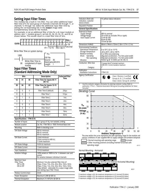
<strong>FLEX</strong> I/O <strong>and</strong> <strong>FLEX</strong> <strong>Integra</strong> Product Data 48V dc 16 Sink Input Module Cat. No. 1794-IC16 87Setting Input Filter TimesThis module has a built-in 1ms filter. You can select additional inputfilter time (FT) for each group of channels (channels 00 through 11, orchannels 12 through 15). Select the additional input filter time bysetting the corresponding bits in the output image table(complementary word) for the module.For example, to set an additional filter of 4ms for a dc input module ataddress rack 1, module group 0, set bits 05, 04, 03, 02, 01, <strong>and</strong> 00 asshown below. This would result in a total filter time of 5ms.O:010Write Filter Time on system startup.I:000Input Filter Times(St<strong>and</strong>ard Addressing Mode Only)Bits Description Selected Filter02 01 00 Filter Time for Inputs 00-11(00-13)Time05 04 03 Filter Time for Inputs 12-15(14-17)0 0 0 Filter Time 0 (default) 256µs0 0 1 Filter Time 1 512µs0 1 0 Filter Time 2 1ms0 1 1 Filter Time 3 2ms1 0 0 Filter Time 4 4ms1 0 1 Filter Time 5 8ms1 1 0 Filter Time 6 16ms1 1 1 Filter Time 7 32msSpecifications - 1794-IC16Number of Inputs16 (1 group of 16), non-isolated, sinkingModule LocationCat. No. 1794-TB3 or -TB3S Terminal Base UnitMountingRefer to derating curveON-State Voltage30V dc minimum;48V dc nominal;60V dc maximumON-State Current2.0mA minimum;5.0mA nominal at 48V dc;11.0mA maximumOFF-State Voltage10.0V dc maximumOFF-State Current1.5mA minimumInput Impedance11K Ω maximumIsolation Voltage100% tested at 1900V dc for 1s between user <strong>and</strong>systemNo isolation between individual channelsMaximum InputFilter TimesOFF to ONON to OFF15 14 13 12 11 10 09 08 07 06 05 04 03 02 01 001 0 0 1 0 000Flexbus Current (max)Power DissipationThermal DissipationWrite Filter Time tocomplement of inputmodule.FT1 = 12-15FT0 = 00-11FLLFill FileSource 36Destination#O:010Length 1Dec.=44 Octalor 36Decimal40843Minimum 1ms plus selected filter time of:256µs, 512µs, 1ms, 2ms, 4ms, 8ms, 16ms, 32ms256µs, 512µs, 1ms, 2ms, 4ms, 8ms, 16ms, 32ms256µs default - selectable thru output image table(see Setting Input Filter Times)25mAMaximum 6.4W @ 60V dcMaximum 21.9 BTU/hr @ 60V dcIndicators (field sideindication, customerdevice driven)Keyswitch Position 2General SpecificationsExternal dc PowerSupply VoltageVoltage RangeInput Supply CurrentDimensions HxWxDEnvironmental ConditionsOperational TemperatureStorage TemperatureRelative HumidityShock OperatingNon-operatingVibrationConductors Wire SizeCategoryPublicationInstallation Instructions 1794-5.53Agency CertificationDerating Curve16 yellow status indicators48V dc nominal30 to 60V dc (includes 5% ac ripple)51mA @ 30V82mA @ 48V107mA @ 60V46mm x 94mm x 53mm (1.8in x 3.7in x 2.1in)0 to 55 o C (32 to 131 o F)-40 to 85 o C (-40 to 185 o F)5 to 95% noncondensing30g peak acceleration, 11(±1)ms pulse width50g peak acceleration, 11(±1)ms pulse widthTested 5g @ 10-500Hz per IEC 68-2-612 gauge (4mm 2 ) str<strong>and</strong>ed maximum3/64 inch (1.2mm) insulation maximum2 1Class I Division 2 certifiedGroups A, B, C, D certifiedClass I Zone 2 Group IIC certified1 Use this conductor category information for planning conductor routing. Refer topublication 1770-4.1, “Industrial Automation Wiring <strong>and</strong> Grounding Guidelines for NoiseImmunity.”6055V in50On-stateVoltage45(V dc)40353029 410 10 20 30 40 50 55 60Ambient Temperature o CThe area within the curve represents the safe operating range for the module undvarious conditions of user supplied 48V dc supply voltages <strong>and</strong> ambient temperatu= Normal mounting safe operating range, included= Other mounting positions (including inverted horizontal) safeoperating range)Normal Mounting - HorizontalOther Mounting (including Vertical <strong>and</strong> Inverted Horizontal Mounting)If maximum voltage is 60, the maximum temperature is 41 (normal) 29 (other).If maximum voltage is 55, the maximum temperature is 55 (normal) 42 (other).If maximum voltage is 50, the maximum temperature is 55 (normal) 55 (other).4022141119Publication 1794-2.1 - January 2000


