


Create successful ePaper yourself
Turn your PDF publications into a flip-book with our unique Google optimized e-Paper software.
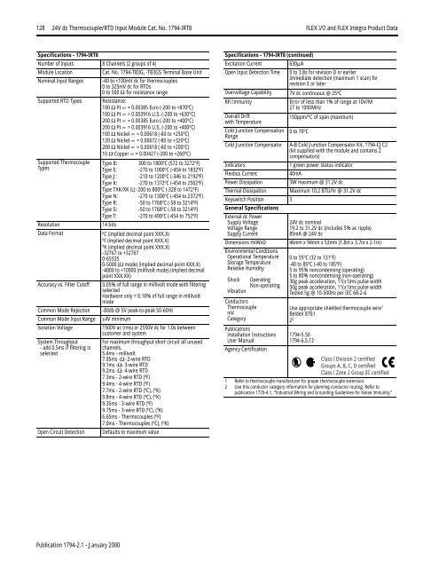
128 24V dc Thermocouple/RTD Input Module Cat. No. 1794-IRT8 <strong>FLEX</strong> I/O <strong>and</strong> <strong>FLEX</strong> <strong>Integra</strong> Product DataSpecifications - 1794-IRT8Number of Inputs 8 Channels (2 groups of 4)Module LocationCat. No. 1794-TB3G, -TB3GS Terminal Base UnitNominal Input Ranges -40 to +100mV dc for thermocouples0 to 325mV dc for RTDs0 to 500 Ω for resistance rangeSupported RTD Types Resistance:100 Ω Pt ∝ = 0.00385 Euro (-200 to +870 o C)100 Ω Pt ∝ = 0.003916 U.S. (-200 to +630 o C)200 Ω Pt ∝ = 0.00385 Euro (-200 to +400 o C)200 Ω Pt ∝ = 0.003916 U.S. (-200 to +400 o C)100 Ω Nickel ∝ = 0.00618 (-60 to +250 o C)120 Ω Nickel ∝ = 0.00672 (-80 to +320 o C)200 Ω Nickel ∝ = 0.00618 (-60 to +200 o C)10 Ω Copper ∝ = 0.00427 (-200 to +260 o C)Supported ThermocoupleTypesResolutionData FormatAccuracy vs. Filter CutoffCommon Mode RejectionCommon Mode Input RangeIsolation VoltageSystem Throughput- add 0.5ms if filtering isselectedOpen Circuit DetectionType B: 300 to 1800 o C (572 to 3272 o F)Type E: -270 to 1000 o C (-454 to 1832 o F)Type J: -210 to 1200 o C (-346 to 2192 o F)Type K: -270 to 1372 o C (-454 to 2502 o F)Type TXK/XK (L):-200 to 800 o C (-328 to 1472 o F)Type N: -270 to 1300 o C (-454 to 2372 o F)Type R: -50 to 1768 o C (-58 to 3214 o F)Type S: -50 to 1768 o C (-58 to 3214 o F)Type T: -270 to 400 o C (-454 to 752 o F)14 bitso C (implied decimal point XXX.X)o F (implied decimal point XXX.X)o K (implied decimal point XXX.X)-32767 to +327670-655350-5000 (Ω mode) (implied decimal point XXX.X)-4000 to +10000 (millivolt mode) (implied decimalpoint XXX.XX)0.05% of full range in millivolt mode with filteringselectedHardware only = 0.10% of full range in millivoltmode-80db @ 5V peak-to-peak 50-60Hz±4V minimum1500V ac (rms) or 2550V dc for 1.0s betweencustomer <strong>and</strong> systemFor maximum throughput short circuit all unusedchannels.5.4ms - millivolt7.05ms -Ω- 2-wire RTD9.1ms -Ω- 3-wire RTD9.2ms -Ω- 4-wire RTD7.3ms - 2-wire RTD ( o F)9.4ms - 4-wire RTD ( o F)7.7ms - 2-wire RTD ( o C), ( o K)9.8ms - 4-wire RTD ( o C), ( o K)9.35ms - 3-wire RTD ( o F)9.75ms - 3-wire RTD ( o C), ( o K)6.65ms - Thermocouples ( o F)7.0ms - Thermocouples ( o C), ( o K)Defaults to maximum valueSpecifications - 1794-IRT8 (continued)Excitation Current 630µAOpen Input Detection Time 0 to 3.8s for revision D or earlierImmediate detection (maximum 1 scan) forrevision E or laterOvervoltage Capability 7V dc continuous @ 25 o CRFI ImmunityError of less than 1% of range at 10V/M27 to 1000MHzOverall Driftwith Temperature150ppm/ o C of span (maximum)Cold Junction CompensationRange0 to 70 o CCold Junction Compensator A-B Cold Junction Compensator Kit, 1794-CJC2(kit supplied with the module <strong>and</strong> contains 2compensators)Indicators1 green power status indicatorFlexbus Current40mAPower Dissipation3W maximum @ 31.2V dcThermal Dissipation Maximum 10.2 BTU/hr @ 31.2V dcKeyswitch Position 3General SpecificationsExternal dc PowerSupply VoltageVoltage RangeSupply CurrentDimensions HxWxDEnvironmental ConditionsOperational TemperatureStorage TemperatureRelative HumidityShockVibrationConductorsThermocouplemVCategoryOperatingNon-operatingPublicationsInstallation InstructionsUser ManualAgency Certification24V dc nominal19.2 to 31.2V dc (includes 5% ac ripple)85mA @ 24V dc46mm x 94mm x 53mm (1.8in x 3.7in x 2.1in)0 to 55 o C (32 to 131 o F)-40 to 85 o C (-40 to 185 o F)5 to 95% noncondensing (operating)5 to 80% noncondensing (non-operating)30g peak acceleration, 11(±1)ms pulse width50g peak acceleration, 11(±1)ms pulse widthTested 5g @ 10-500Hz per IEC 68-2-6Use appropriate shielded thermocouple wire 1Belden 87612 21794-5.501794-6.5.12Class I Division 2 certifiedGroups A, B, C, D certifiedClass I Zone 2 Group IIC certified1 Refer to thermocouple manufacturer for proper thermocouple extension.2 Use this conductor category information for planning conductor routing. Refer topublication 1770-4.1, “Industrial Wiring <strong>and</strong> Grounding Guidelines for Noise Immunity.”Publication 1794-2.1 - January 2000


