


You also want an ePaper? Increase the reach of your titles
YUMPU automatically turns print PDFs into web optimized ePapers that Google loves.
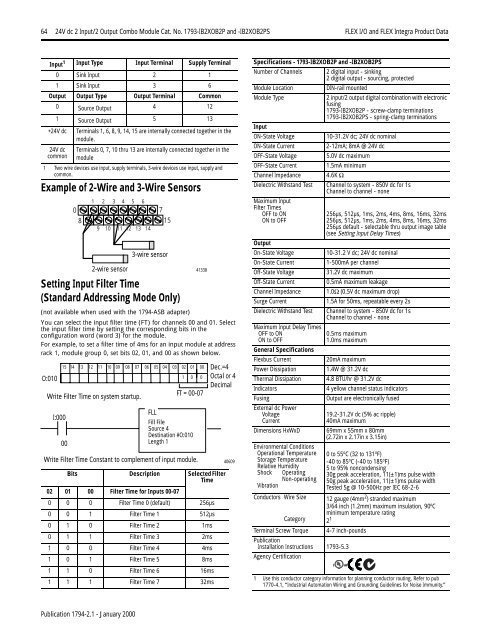
64 24V dc 2 Input/2 Output Combo Module Cat. No. 1793-IB2XOB2P <strong>and</strong> -IB2XOB2PS <strong>FLEX</strong> I/O <strong>and</strong> <strong>FLEX</strong> <strong>Integra</strong> Product DataInput 1 Input Type Input Terminal Supply Terminal0 Sink Input 2 11 Sink Input 3 6Output Output Type Output Terminal Common0 Source Output 4 121 Source Output 5 13+24V dc Terminals 1, 6, 8, 9, 14, 15 are internally connected together in themodule.24V dccommonTerminals 0, 7, 10 thru 13 are internally connected together in themodule1 Two wire devices use input, supply terminals, 3-wire devices use input, supply <strong>and</strong>common.Example of 2-Wire <strong>and</strong> 3-Wire Sensors1 2 3 4 5 60 78 159 10 11 12 13 143-wire sensor2-wire sensor 41338Setting Input Filter Time(St<strong>and</strong>ard Addressing Mode Only)(not available when used with the 1794-ASB adapter)You can select the input filter time (FT) for channels 00 <strong>and</strong> 01. Selectthe input filter time by setting the corresponding bits in theconfiguration word (word 3) for the module.For example, to set a filter time of 4ms for an input module at addressrack 1, module group 0, set bits 02, 01, <strong>and</strong> 00 as shown below.O:01015 14 13 12 11 10 09 08 07 06 05 04 03 02 01 001 0 0Write Filter Time on system startup.I:00000FT = 00-07FLLFill FileSource 4Destination #O:010Length 1Write Filter Time Constant to complement of input module.Dec.=4Octal or 4DecimalBits Description Selected FilterTime02 01 00 Filter Time for Inputs 00-070 0 0 Filter Time 0 (default) 256µs0 0 1 Filter Time 1 512µs0 1 0 Filter Time 2 1ms0 1 1 Filter Time 3 2ms1 0 0 Filter Time 4 4ms1 0 1 Filter Time 5 8ms1 1 0 Filter Time 6 16ms1 1 1 Filter Time 7 32ms40609Specifications - 1793-IB2XOB2P <strong>and</strong> -IB2XOB2PSNumber of Channels 2 digital input - sinking2 digital output - sourcing, protectedModule LocationDIN-rail mountedModule Type2 input/2 output digital combination with electronicfusing1793-IB2XOB2P - screw-clamp terminations1793-IB2XOB2PS - spring-clamp terminationsInputON-State Voltage10-31.2V dc; 24V dc nominalON-State Current2-12mA; 8mA @ 24V dcOFF-State Voltage 5.0V dc maximumOFF-State Current 1.5mA minimumChannel Impedance 4.6K ΩDielectric Withst<strong>and</strong> Test Channel to system - 850V dc for 1sChannel to channel - noneMaximum InputFilter TimesOFF to ONON to OFFOutputOn-State VoltageOn-State CurrentOff-State VoltageOff-State CurrentChannel ImpedanceSurge CurrentDielectric Withst<strong>and</strong> TestMaximum Input Delay TimesOFF to ONON to OFFGeneral SpecificationsFlexbus CurrentPower DissipationThermal DissipationIndicatorsFusingExternal dc PowerVoltageCurrentDimensions HxWxDEnvironmental ConditionsOperational TemperatureStorage TemperatureRelative HumidityShock OperatingNon-operatingVibrationConductors Wire SizeCategoryTerminal Screw Torque256µs, 512µs, 1ms, 2ms, 4ms, 8ms, 16ms, 32ms256µs, 512µs, 1ms, 2ms, 4ms, 8ms, 16ms, 32ms256µs default - selectable thru output image table(see Setting Input Delay Times)10-31.2 V dc; 24V dc nominal1-500mA per channel31.2V dc maximum0.5mA maximum leakage1.0Ω (0.5V dc maximum drop)1.5A for 50ms, repeatable every 2sChannel to system - 850V dc for 1sChannel to channel - none0.5ms maximum1.0ms maximumPublicationInstallation Instructions 1793-5.3Agency Certification20mA maximum1.4W @ 31.2V dc4.8 BTU/hr @ 31.2V dc4 yellow channel status indicatorsOutput are electronically fused19.2-31.2V dc (5% ac ripple)40mA maximum69mm x 55mm x 80mm(2.72in x 2.17in x 3.15in)0 to 55 o C (32 to 131 o F)-40 to 85 o C (-40 to 185 o F)5 to 95% noncondensing30g peak acceleration, 11(±1)ms pulse width50g peak acceleration, 11(±1)ms pulse widthTested 5g @ 10-500Hz per IEC 68-2-612 gauge (4mm 2 ) str<strong>and</strong>ed maximum3/64 inch (1.2mm) maximum insulation, 90 o Cminimum temperature rating2 14-7 inch-pounds1 Use this conductor category information for planning conductor routing. Refer to pub1770-4.1, “Industrial Automation Wiring <strong>and</strong> Grounding Guidelines for Noise Immunity.”Publication 1794-2.1 - January 2000


