


Create successful ePaper yourself
Turn your PDF publications into a flip-book with our unique Google optimized e-Paper software.
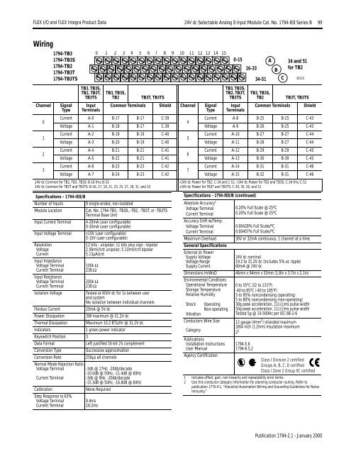
<strong>FLEX</strong> I/O <strong>and</strong> <strong>FLEX</strong> <strong>Integra</strong> Product Data 24V dc Selectable Analog 8 Input Module Cat. No. 1794-IE8 Series B 99WiringChannel01231794-TB31794-TB3S1794-TB21794-TB3T1794-TB3TSSignalTypeTB3, TB3S,TB2, TB3T,TB3TSInputTerminalsTB3, TB3S,TB2TB3T, TB3TSCommon Terminals Shield Channel SignalTypeTB3, TB3S,TB2, TB3T,TB3TSInputTerminalsTB3, TB3S,TB2Common TerminalsTB3T, TB3TSCurrent A-0 B-17 B-17 C-39Current A-8 B-25 B-25 C-434Voltage A-1 B-18 B-17 C-39 Voltage A-9 B-26 B-25 C-43Current A-2 B-19 B-19 C-40Current A-10 B-27 B-27 C-445Voltage A-3 B-20 B-19 C-40 Voltage A-11 B-28 B-27 C-44Current A-4 B-21 B-21 C-41Current A-12 B-29 B-29 C-456Voltage A-5 B-22 B-21 C-41 Voltage A-13 B-30 B-39 C-45Current A-6 B-23 B-23 C-42Current A-14 B-31 B-31 C-467Voltage A-7 B-24 B-23 C-42 Voltage A-15 B-32 B-31 C-4624V dc Common for TB2, TB3, TB3S: B-16 thru B-3324V dc Common for TB3T <strong>and</strong> TB3TS: B-16, 17, 19, 21, 23, 25, 27, 29, 31, <strong>and</strong> 330 1 2 3 4 5 6 7 8 9 10 11 12 13 14 150 1 2 3 4 5 6 7 8 9 10 11 12 13 14 1516 17 18 19 20 21 22 23 24 25 26 27 28 29 30 31 32 330-1534 35 36 37 38 39 40 41 42 43 44 45 46 47 48 49 50 5116-3334-51+24V dc Power for TB2: C-34 <strong>and</strong> C-51; +24V dc Power for TB3 <strong>and</strong> TB3S: C-34 thru C-51+24V dc Power for TB3T <strong>and</strong> TB3TS: C-34, 35, 50, <strong>and</strong> 51AB34 <strong>and</strong> 51for TB2C 30233ShieldSpecifications - 1794-IE8/BNumber of Inputs8 single-ended, non-isolatedModule LocationCat. No. 1794-TB3, -TB3S, -TB2, -TB3T, or -TB3TSTerminal Base UnitInput Current Terminal 4-20mA (user configurable)0-20mA (user configurable)Input Voltage Terminal ±10V (user configurable)0-10V (user configurable)ResolutionVoltageCurrentInput ImpedanceVoltage TerminalCurrent TerminalInput ResistanceVoltage TerminalCurrent TerminalIsolation Voltage12 bits - unipolar; 11 bits plus sign - bipolar2.56mV/cnt unipolar; 5.13mV/cnt bipolar5.13µA/cnt100k Ω238 Ω200k Ω238 ΩTested at 850V dc for 1s between user<strong>and</strong> systemNo isolation between individual channels20mA @ 5V dc3W maximum @ 31.2V dcMaximum 10.2 BTU/hr @ 31.2V dc1 green power indicatorFlexbus CurrentPower DissipationThermal DissipationIndicatorsKeyswitch Position 3Data FormatLeft justified 16-bit 2’s complementConversion TypeSuccessive approximationConversion Rate256µs all channelsNormal Mode Rejection RatioVoltage TerminalCurrent TerminalCalibrationStep Response to 63%Voltage TerminalCurrent Terminal-3db @ 17Hz; -20db/decade-10.0dB @ 50Hz, -11.4dB @ 60Hz-3db @ 9Hz; -20db/decade-15.3dB @ 50Hz, -16.8dB @ 60HzNone Required9.4ms18.2msSpecifications - 1794-IE8/B (continued)Absolute Accuracy 1Voltage TerminalCurrent TerminalAccuracy Drift w/Temp.Voltage TerminalCurrent TerminalMaximum OverloadGeneral SpecificationsExternal dc PowerSupply VoltageVoltage RangeSupply CurrentDimensions HxWxDEnvironmental ConditionsOperational TemperatureStorage TemperatureRelative HumidityShock OperatingNon-operatingVibrationConductors Wire SizeCategoryPublicationsInstallation InstructionsUser ManualAgency Certification0.20% Full Scale @ 25 o C0.20% Full Scale @ 25 o C0.00428% Full Scale/ o C0.00407% Full Scale/ o C30V or 32mA continuous, 1 channel at a time24V dc nominal19.2 to 31.2V dc (includes 5% ac ripple)60mA @ 24V dc46mm x 94mm x 53mm (1.8in x 3.7in x 2.1in)0 to 55 o C (32 to 131 o F)-40 to 85 o C (-40 to 185 o F)5 to 95% noncondensing (operating)5 to 80% noncondensing (non-operating)30g peak acceleration, 11(±1)ms pulse width50g peak acceleration, 11(±1)ms pulse widthTested 5g @ 10-500Hz per IEC 68-2-612 gauge (4mm 2 ) str<strong>and</strong>ed maximum3/64 inch (1.2mm) insulation maximum2 21794-5.61794-6.5.2Class I Division 2 certifiedGroups A, B, C, D certifiedClass I Zone 2 Group IIC certified1 Includes offset, gain, non-linearity <strong>and</strong> repeatability error terms.2 Use this conductor category information for planning conductor routing. Refer topublication 1770-4.1, “Industrial Automation Wiring <strong>and</strong> Grounding Guidelines for NoiseImmunity.”Publication 1794-2.1 - January 2000


