Instruction Manual - Sierra Instruments
Instruction Manual - Sierra Instruments
Instruction Manual - Sierra Instruments

Create successful ePaper yourself
Turn your PDF publications into a flip-book with our unique Google optimized e-Paper software.
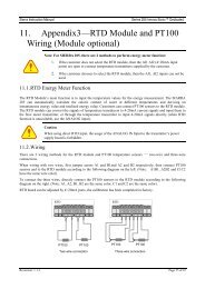
<strong>Sierra</strong> <strong>Instruments</strong> <strong>Instruction</strong> <strong>Manual</strong>SmartTrak ® 100 SeriesFigure 2-3: HD DB-15 Connector Pin Configuration (on the instrument)Figure 2-4: Wiring Definitions for Optional Communication CablePin # Wire Color in Cable Function1. Brown Analog Ground/Output2. Red 0-5 VDC Output (or 0-10, 1-5 VDC)3. Orange Analog Ground/RS2324. Pink Valve Override Purge5. Yellow Power Return (-)6. Green Power Input (+)7. Green/White RS-232 Transmit (out)8. Blue Setpoint9. Purple Not Used10. Gray Analog Ground/Setpoint11. White Reference Voltage(5 VDC External Setpoint & Valve Purge)12. Black Valve Override Close13. Brown/white RS-232 Receive (in)14. Red/white 4-20 mA Output15. Red/Black Not UsedShield Wire(no insulation)Chassis (Earth) GroundNOTE: Pins 1, 3, and 10 are connected together inside theinstrument. Do not tie these grounds together outside theinstrument. Must have one connection per analog ground.Recommended use listed.18