Installation Instructions for a âPairâ of gates...
Installation Instructions for a âPairâ of gates...
Installation Instructions for a âPairâ of gates...

You also want an ePaper? Increase the reach of your titles
YUMPU automatically turns print PDFs into web optimized ePapers that Google loves.
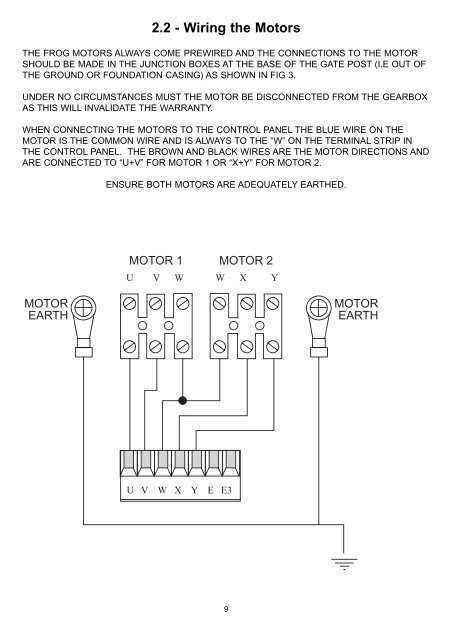
2.2 - Wiring the MotorsTHE FROG MOTORS ALWAYS COME PREWIRED AND THE CONNECTIONS TO THE MOTORSHOULD BE MADE IN THE JUNCTION BOXES AT THE BASE OF THE GATE POST (I.E OUT OFTHE GROUND OR FOUNDATION CASING) AS SHOWN IN FIG 3.UNDER NO CIRCUMSTANCES MUST THE MOTOR BE DISCONNECTED FROM THE GEARBOXAS THIS WILL INVALIDATE THE WARRANTY.WHEN CONNECTING THE MOTORS TO THE CONTROL PANEL THE BLUE WIRE ON THEMOTOR IS THE COMMON WIRE AND IS ALWAYS TO THE “W” ON THE TERMINAL STRIP INTHE CONTROL PANEL. THE BROWN AND BLACK WIRES ARE THE MOTOR DIRECTIONS ANDARE CONNECTED TO “U+V” FOR MOTOR 1 OR “X+Y” FOR MOTOR 2.ENSURE BOTH MOTORS ARE ADEQUATELY EARTHED.MOTOR 1 MOTOR 2U V W W X YMOTOREARTHMOTOREARTHU V W X Y E E39