- Page 1 and 2:
HP ProBook 4320s Notebook PCHP ProB
- Page 3:
MSG Revision historyRevision Public
- Page 7 and 8:
Table of contents1 Product descript
- Page 9 and 10:
Computer Setup menus ..............
- Page 11 and 12:
1 Product descriptionCategory Descr
- Page 13 and 14:
Category Description HPProBook4320s
- Page 15 and 16:
Category Description HPProBook4320s
- Page 17 and 18:
Category Description HPProBook4320s
- Page 19 and 20:
Category Description HPProBook4320s
- Page 21 and 22:
Top componentsTouchPadComponentDesc
- Page 23 and 24:
Buttons, speakers, switches, and fi
- Page 25 and 26:
Front componentsComponentDescriptio
- Page 27 and 28:
Left-side componentsComponentDescri
- Page 29 and 30:
DisplayNOTE:Your computer may look
- Page 31 and 32:
Additional hardware componentsCompo
- Page 33 and 34:
Computer major componentsComputer m
- Page 35 and 36:
Item Description Spare part number
- Page 37 and 38:
Item Description Spare part number(
- Page 39 and 40:
Item Description Spare part numberF
- Page 41 and 42:
Display assembly componentsItem Des
- Page 43 and 44:
Plastics KitItem Description Spare
- Page 45 and 46:
Mass storage devicesItem Descriptio
- Page 47 and 48:
DescriptionRubber kit (includes dis
- Page 49 and 50:
Spare partnumberDescription504593-0
- Page 51 and 52:
Spare partnumberDescription599526-0
- Page 53 and 54:
Spare partnumber599572-BG1599572-DD
- Page 55 and 56:
4 Removal and replacement procedure
- Page 57 and 58:
Grounding guidelinesElectrostatic d
- Page 59 and 60:
Equipment guidelinesGrounding equip
- Page 61 and 62:
BatteryDescriptionSpare part number
- Page 63 and 64:
Switch coverDescriptionSpare part n
- Page 65 and 66:
KeyboardDescriptionSpare part numbe
- Page 67 and 68:
Memory moduleDescriptionSpare part
- Page 69 and 70:
Optical driveNOTE:All optical drive
- Page 71 and 72: Power connector boardDescriptionSpa
- Page 73 and 74: 4. Remove the speaker cable from th
- Page 75 and 76: 4. Remove the WWAN module (3) by pu
- Page 77 and 78: 3. Slide the palm rest to the right
- Page 79 and 80: 4. Remove the hard drive (4) from t
- Page 81 and 82: WLAN moduleDescriptionSpare part nu
- Page 83 and 84: Remove the WLAN module:1. Position
- Page 85 and 86: 4. Remove the Bluetooth module cabl
- Page 87 and 88: 4. Lift the right edge of the heat
- Page 89 and 90: NOTE: The thermal material must be
- Page 91 and 92: 3. Lift the processor (2) straight
- Page 93 and 94: Display assemblyNOTE:The display as
- Page 95 and 96: CAUTION: Support the display assemb
- Page 97 and 98: 6. If it is necessary to replace th
- Page 99 and 100: 11. Release the cable from the disp
- Page 101 and 102: Top coverDescriptionSpare part numb
- Page 103 and 104: Modem moduleDescriptionSpare part n
- Page 105 and 106: System boardNOTE:The system board s
- Page 107 and 108: USB connector boardDescriptionSpare
- Page 109 and 110: Modem module cableNOTE: The modem m
- Page 111 and 112: 5 Computer SetupComputer Setup in W
- Page 113 and 114: Your preferences go into effect whe
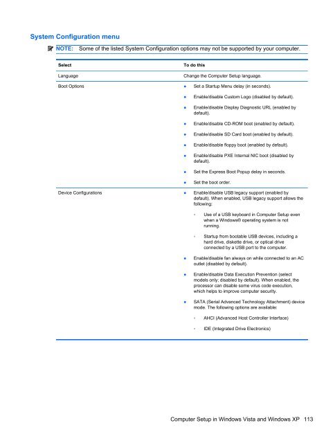
- Page 115 and 116: System Configuration menuNOTE:Some
- Page 117 and 118: SelectTo do thisBuilt-in device opt
- Page 119 and 120: To exit Computer Setup menus, choos
- Page 121: Security menuNOTE:Some of the menu
- Page 125 and 126: SelectSet Security LevelRestore Sec
- Page 127 and 128: Restoring factory settings in Compu
- Page 129 and 130: Diagnostics menuSelectHDD Self-Test
- Page 131 and 132: SelectTo do thisBuilt-in device opt
- Page 133 and 134: 33.8-cm (13.3-in) models 35.6-cm (1
- Page 135 and 136: Hard drive specifications500-GB* 32
- Page 137 and 138: DVD±RW SuperMulti Double-Layer Dri
- Page 139 and 140: System resource specificationsYou c
- Page 141 and 142: ●Save customized settings that ap
- Page 143 and 144: Backup and recovery in Windows Vist
- Page 145 and 146: Using f11NOTE: Windows includes the
- Page 147 and 148: Backup and recovery in Windows XPOv
- Page 149 and 150: Linux backup and recoveryUse the in
- Page 151 and 152: Audio-out (headphone)PinSignal1 Aud
- Page 153 and 154: HDMIPinSignal1 Transition minimized
- Page 155 and 156: RJ-45 (network)PinSignal1 Transmit
- Page 157 and 158: eSATA/USBPinSignal1 USB +5 VDC2 USB
- Page 159 and 160: Requirements for specific countries
- Page 161 and 162: Perform the following steps to disa
- Page 163 and 164: 10. Remove the display panel frame
- Page 165 and 166: 18. Remove the backlight from the b
- Page 167 and 168: diskette driveprecautions 46product
- Page 169: SSATA (Serial AdvancedTechnology At