Grundoram Manual (PDF 1.7MB) - TT Technologies Inc.
Grundoram Manual (PDF 1.7MB) - TT Technologies Inc.
Grundoram Manual (PDF 1.7MB) - TT Technologies Inc.
- No tags were found...

You also want an ePaper? Increase the reach of your titles
YUMPU automatically turns print PDFs into web optimized ePapers that Google loves.
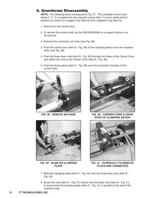
A. <strong>Grundoram</strong> DisassemblyNOTE: The following items correspond to Fig. 37. The complete control stud(Items 5, 6, 7) is pushed into the machine casing (Item 1) and is safely held inposition by means of a support ring (Item 8) and a segment ring (Item 9).1. Removal of the control stud.2. To remove the control stud, lay the GRUNDORAM on a support frame or onthe ground.3. Remove the connection air hose (see Fig. 38).4. Push the carrier cone (Item A - Fig. 39) of the clamping device over the machinebody (see Fig. 39).5. Push the three draw rods (Item B - Fig. 39) through the holes of the Carrier Coneand attach the nuts at the Carrier Cone (Item A - Fig. 39).6. Push the thrust piece (Item C - Fig. 39) over the connection threads of thecontrol tube.BACBBFIG. 38: REMOVE AIR HOSEFIG. 39: CARRIER CONE & DRAWRODS OF CLAMPING DEVICEBDBCBBAEDFBBFIG. 40: SLIDE ON CLAMPINGPLATEFIG. 41: HYDRAULIC CYLINDER INPLACE AND CONNECTED26 <strong>TT</strong> TECHNOLOGIES, INC.7. Slide the clamping plate (Item D - Fig. 40) onto the three draw rods (Item B -Fig. 40).8. Screw the nuts (Item E - Fig. 41) evenly onto the draw rods (Item B - Fig. 41)to ensure that the clamping plate (Item D - Fig. 41) is parallel to the end of themachine body.