- Page 1 and 2:
GRANDMASTER4000Switch MachineInstal
- Page 3 and 4:
LIST OF EFFECTIVE PAGESP2444, Grand
- Page 5 and 6:
TABLE OF CONTENTSSECTION 1 - GENERA
- Page 7 and 8:
TABLE OF CONTENTS (Cont.)SECTION 4
- Page 9 and 10:
LIST OF FIGURESFigure No. Descripti
- Page 11 and 12:
LIST OF TABLESTable No. Description
- Page 13 and 14:
PREFACEABOUT THE MANUALThis manual
- Page 15 and 16:
SECTION 1GENERAL DESCRIPTIONSCOPE O
- Page 17 and 18:
Electronic ClutchThe amplifier, uti
- Page 19 and 20:
REAR COVER(GM050-006-00)HAND THROWM
- Page 21 and 22:
30:1 GearboxThe 30:1 gearbox, flex
- Page 23 and 24:
MOTOR(GM050-020-00)AMPLIFIER(GM050-
- Page 25 and 26:
Safety at Trackside1. Check for a s
- Page 27 and 28:
SECTION 2THEORY OF OPERATIONINTRODU
- Page 29 and 30:
The second is the AMPLIFIER, the de
- Page 31 and 32:
POINT DETECTIONThere are five modul
- Page 33 and 34:
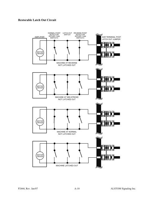
LATCHOUTLatchout is an indication o
- Page 35 and 36:
9. The latchout is reset - Latchout
- Page 37 and 38:
SECTION 3INSTALLATIONGENERALThere a
- Page 39 and 40:
Switch LayoutThe following describe
- Page 41 and 42:
Electrical WiringThe switch machine
- Page 43 and 44:
Power TB1-2 - TB1-2Power TB1-3 TB1-
- Page 45 and 46:
Switch Machine Connecting and Adjus
- Page 47 and 48:
4. Hand throw, crank, or manually o
- Page 49 and 50:
1. Position the spoon gauge into th
- Page 51 and 52:
2. Insert the hand crank and check
- Page 53 and 54:
GRSHand-ThrowThis procedure is used
- Page 55 and 56:
LEFT-HAND OR RIGHT-HAND CONFIGURATI
- Page 57 and 58:
Hand-throw Lever and Latch StandsTh
- Page 59 and 60:
BEFORE PLACING MACHINE IN SERVICEPe
- Page 61 and 62:
SECTION 4SCHEDULED MAINTENANCEINTRO
- Page 63 and 64:
SITE INSPECTIONA site inspection co
- Page 65 and 66:
Wide-Notch Lock Rod:1. Insert an ob
- Page 67 and 68: MOTOR(GM050-020-00)AMPLIFIER(GM050-
- Page 69 and 70: LOCK ROD AND POINT DETECTOR ADJUSTM
- Page 71 and 72: POINT-DETECTORSWITCH LEVERROTARY CA
- Page 73 and 74: SECTION 5TROUBLESHOOTINGPHILOSOPHYT
- Page 75 and 76: Table 5-2. Trackside Noted Symptoms
- Page 77 and 78: Table 5-3. Amplifier LED DisplaysAm
- Page 79 and 80: SECTION 6CORRECTIVE MAINTENANCEPURP
- Page 81 and 82: Cross BraceBoth cross braces are at
- Page 83 and 84: MOTORWIRINGCONNECTORPAN HEADSCREWS
- Page 85 and 86: Removal Procedure1. Remove motor en
- Page 87 and 88: Removal Procedure1. Remove motor en
- Page 89 and 90: HANDCRANKLATCHHANDTHROWLATCHSTANDSC
- Page 91 and 92: Main DrivePerform the following pro
- Page 93 and 94: Lock RodPerform the following proce
- Page 95 and 96: Point Detector Switch ModulePerform
- Page 97 and 98: Removal Procedure1. Remove all conn
- Page 99 and 100: Cam BarPerform the following proced
- Page 101 and 102: SECTION 7PARTS CATALOGGENERALThis s
- Page 103 and 104: 34-7230324044-76-7810-11 66-69 45 9
- Page 105 and 106: Table 7-1. ALSTOM Model GM4000 Swit
- Page 107 and 108: Table 7-1. ALSTOM Model GM4000 Swit
- Page 109 and 110: Table 7-3. ALSTOM Model GM4000 Swit
- Page 111 and 112: WIRING AND CIRCUIT APPLICATIONS3-Wi
- Page 113 and 114: 3-Wire Configuration(For Replacemen
- Page 115 and 116: 4-Wire Configuration (Continued)(Fo
- Page 117: 5-Wire Configuration (Continued)(Fo
- Page 121 and 122: INSTALLATION AND SPACE REQUIREMENTS
- Page 123 and 124: Typical Polarized Switch Repeater R
- Page 125 and 126: Typical Polarized Switch Repeater C
- Page 127 and 128: Typical Neutral Switch Repeater Cir
- Page 129 and 130: Typical Neutral Switch Repeater Rel
- Page 131: 1POWER2POWER34CONTROL5TB1-67HAND TH