

4000 Switch Machine - Alstom
4000 Switch Machine - Alstom
4000 Switch Machine - Alstom

You also want an ePaper? Increase the reach of your titles
YUMPU automatically turns print PDFs into web optimized ePapers that Google loves.
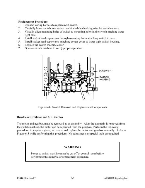
Replacement Procedure1. Connect wiring harness to replacement switch.2. Carefully lower switch into switch machine while checking wire harness clearance.3. Visually align mounting holes of switch to mounting holes in the switch machine watertight case.4. Install socket head cap screws through mounting holes attaching switch to case.5. Install socket head cap screws attaching access cover to water tight switch housing.6. Replace the switch machine cover.7. Operate switch machine to verify proper operation.SCREWS (4)SWITCHHOUSINGFigure 6-4. <strong>Switch</strong> Removal and Replacement ComponentsBrushless DC Motor and 5:1 GearboxThe motor and gearbox must be removed as an assembly. After the assembly is removed fromthe switch machine, the motor can be separated from the gearbox. Perform the followingprocedure, in sequence given, to remove and replace the motor and gearbox assembly. Refer toFigure 6-5 while performing this procedure. No adjustments or special tools are required.WARNINGPower to switch machine must be cut off at control room beforeperforming this removal or replacement procedure.P2444, Rev. Jan/07 6-6ALSTOM Signaling Inc.


