

4000 Switch Machine - Alstom
4000 Switch Machine - Alstom
4000 Switch Machine - Alstom

You also want an ePaper? Increase the reach of your titles
YUMPU automatically turns print PDFs into web optimized ePapers that Google loves.
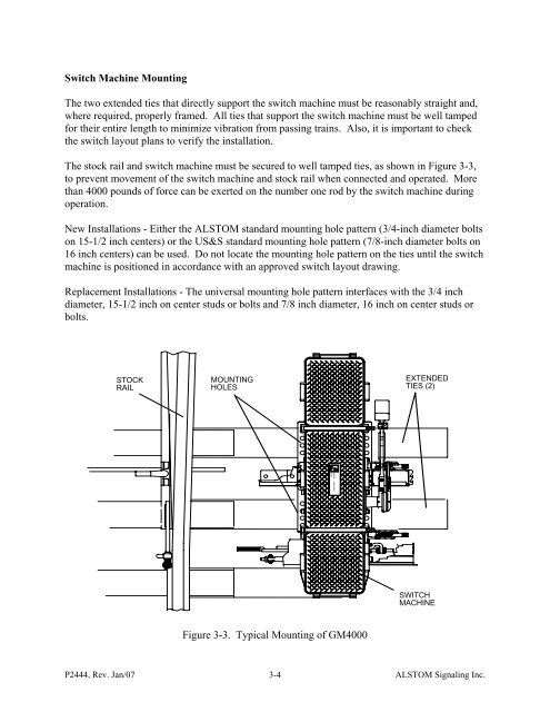
<strong>Switch</strong> <strong>Machine</strong> MountingThe two extended ties that directly support the switch machine must be reasonably straight and,where required, properly framed. All ties that support the switch machine must be well tampedfor their entire length to minimize vibration from passing trains. Also, it is important to checkthe switch layout plans to verify the installation.The stock rail and switch machine must be secured to well tamped ties, as shown in Figure 3-3,to prevent movement of the switch machine and stock rail when connected and operated. Morethan <strong>4000</strong> pounds of force can be exerted on the number one rod by the switch machine duringoperation.New Installations - Either the ALSTOM standard mounting hole pattern (3/4-inch diameter boltson 15-1/2 inch centers) or the US&S standard mounting hole pattern (7/8-inch diameter bolts on16 inch centers) can be used. Do not locate the mounting hole pattern on the ties until the switchmachine is positioned in accordance with an approved switch layout drawing.Replacement Installations - The universal mounting hole pattern interfaces with the 3/4 inchdiameter, 15-1/2 inch on center studs or bolts and 7/8 inch diameter, 16 inch on center studs orbolts.STOCKRAILMOUNTINGHOLESEXTENDEDTIES (2)SASIBSASIBGRSRAILWAYSWITCHMACHINEFigure 3-3. Typical Mounting of GM<strong>4000</strong>P2444, Rev. Jan/07 3-4ALSTOM Signaling Inc.


