

4000 Switch Machine - Alstom
4000 Switch Machine - Alstom
4000 Switch Machine - Alstom

You also want an ePaper? Increase the reach of your titles
YUMPU automatically turns print PDFs into web optimized ePapers that Google loves.
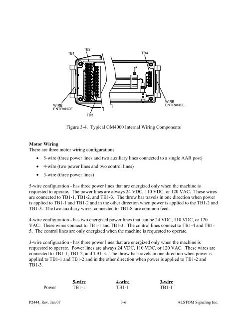
TB1TB2TB4WIREENTRANCETB3WIREENTRANCEFigure 3-4. Typical GM<strong>4000</strong> Internal Wiring ComponentsMotor WiringThere are three motor wiring configurations:• 5-wire (three power lines and two auxiliary lines connected to a single AAR post)• 4-wire (two power lines and two control lines)• 3-wire (three power lines)5-wire configuration - has three power lines that are energized only when the machine isrequested to operate. The power lines are always 24 VDC, 110 VDC, or 120 VAC. These wiresare connected to TB1-1, TB1-2, and TB1-3. The throw bar travels in one direction when poweris applied to TB1-1 and TB1-2 and in the other direction when power is applied to the TB1-2 andTB1-3. The two auxiliary wires, connected to TB1-8, are common feed.4-wire configuration - has two energized power lines that can be 24 VDC, 110 VDC, or 120VAC. These wires connect to TB1-1 and TB1-3. The control lines connect to TB1-4 and TB1-5. The control lines are only energized when the machine is requested to operate.3-wire configuration - has three power lines that are energized only when the machine isrequested to operate. Power lines are always 24 VDC, 110 VDC, or 120 VAC. These wires areconnected to TB1-1, TB1-2, and TB1-3. The throw bar travels in one direction when power isapplied to TB1-1 and TB1-2 and in the other direction when power is applied to TB1-2 andTB1-3.5-wire 4-wire 3-wirePower TB1-1 TB1-1 TB1-1P2444, Rev. Jan/07 3-6ALSTOM Signaling Inc.


