

4000 Switch Machine - Alstom
4000 Switch Machine - Alstom
4000 Switch Machine - Alstom

Create successful ePaper yourself
Turn your PDF publications into a flip-book with our unique Google optimized e-Paper software.
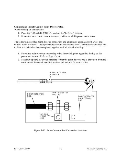
Connect and Initially Adjust Point-Detector RodWhen working on the machine:1. Place the "LOCAL/REMOTE" switch in the “LOCAL” position.2. Rotate the hand crank cover to the open position to inhibit power to the motor.The following describes point-detector connection and adjustment associated with wide- andnarrow-notch lock rods. These procedures assume that connection of the throw bar and lock rodto the track switch has been completed together with all electrical wiring.1. Fasten the point-detector connecting rod to the switch point lug and to the lug on thepoint-detector rod. Refer to Figure 3-10.2. Manually operate the switch machine so that the point-detector rod is drawn out from thetrack side of the switch machine to close and lock the far switch point.POINT-DETECTORROD NECKPOINT-DETECTORRODPOINT-DETECTORROD LUGPOINT-DETECTORCONNECTINGRODSWITCHPOINTLUGFigure 3-10. Point-Detector Rod Connection HardwareP2444, Rev. Jan/07 3-12ALSTOM Signaling Inc.


