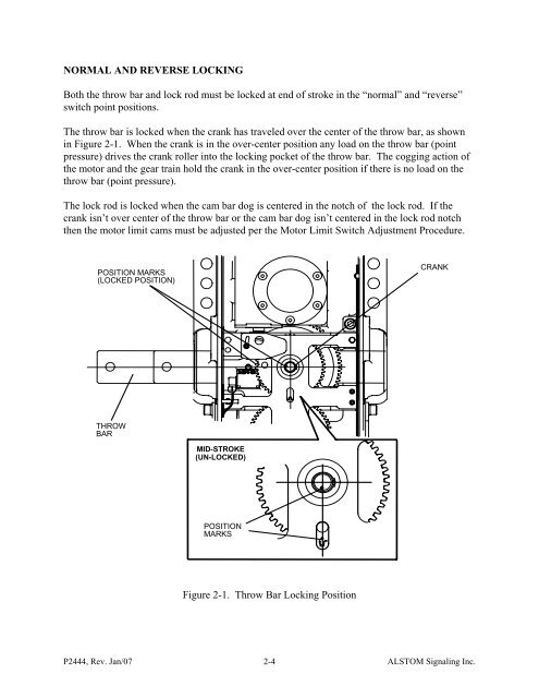
NORMAL AND REVERSE LOCKINGBoth the throw bar and lock rod must be locked at end of stroke in the “normal” and “reverse”switch point positions.The throw bar is locked when the crank has traveled over the center of the throw bar, as shownin Figure 2-1. When the crank is in the over-center position any load on the throw bar (pointpressure) drives the crank roller into the locking pocket of the throw bar. The cogging action ofthe motor and the gear train hold the crank in the over-center position if there is no load on thethrow bar (point pressure).The lock rod is locked when the cam bar dog is centered in the notch of the lock rod. If thecrank isn’t over center of the throw bar or the cam bar dog isn’t centered in the lock rod notchthen the motor limit cams must be adjusted per the Motor Limit <strong>Switch</strong> Adjustment Procedure.POSITION MARKS(LOCKED POSITION)CRANKTHROWBARMID-STROKE(UN-LOCKED)POSITIONMARKSFigure 2-1. Throw Bar Locking PositionP2444, Rev. Jan/07 2-4ALSTOM Signaling Inc.
POINT DETECTIONThere are five modules that interact to perform point detection. They are the point detectorsystem module, the point detector switch module, the point detector rod, the lock rod, and thecam bar. See the module descriptions for a detailed explanation.The point detector switch module contains two “positive break” rotary cam switches. Oneswitch rotates clockwise and one rotates counter-clockwise. A positive break switch contains amechanism that breaks open frozen or welded contacts. Each rotary cam switch consists of sixswitches for indication, shunting, latchout, and continuity checking. <strong>Switch</strong>es 1 and 2 are usedto shunt the NWP and WP coils in the indication relays when the switch machine is unlocked.<strong>Switch</strong>es 3 and 4 are used to indicate that the switch points, switch machine, lock rod, and pointdetector rod are either in, or out of, correspondence. <strong>Switch</strong> number 5 is used for latchout.<strong>Switch</strong> 6 is used for the continuity checking LED.The range of motion for the rotary cam switch is 60 degrees. There is an external spring returnmechanism that returns the switch to the 0 degree position. As the switch rotates, the sixcontacts actuate. See Table 2-1 for detailed switch movement.Table 2-1. <strong>Switch</strong> Movement<strong>Switch</strong>Type 0° 8° 20° 21° 60°1 shunt X-------------------------X2 shunt X-------------------------X3 indicate X-------------------------X4 indicate X----------------X5 latch out X----------------------------------X6 LED X------------------------------(LED on)----------X (LED off)NOTE: X-----X = closed switch<strong>Switch</strong> 6 is used to check the mechanical interface (continuity) between the point detector switchactuating lever and rotary cam switch. When the switch machine is indicating a closed point, theLED is on and at mid-stroke the LED is off.If contacts 3, 4, and 5 are closed, the switch machine is in correspondence and the switchmachine is indicating. <strong>Switch</strong>es 3, 4, and 5 begin to open at 8 degrees. <strong>Switch</strong>es 3, 4, and 5 areopen at 20 degrees. The variance in switch closure is due to tolerances in the manufacturingprocess. <strong>Switch</strong>es 3, 4, and 5 all must be closed before the point detector system indicates.There is a range where the LED is on and the point detector is not indicating. This range occursbetween 8 degrees and 21 degrees, when one of the indicating switches (3, 4, or 5) is open andthe LED switch is closed.P2444, Rev. Jan/07 2-5ALSTOM Signaling Inc.