Introduction to On Board Diagnostics (II)
Introduction to On Board Diagnostics (II)
Introduction to On Board Diagnostics (II)
Create successful ePaper yourself
Turn your PDF publications into a flip-book with our unique Google optimized e-Paper software.
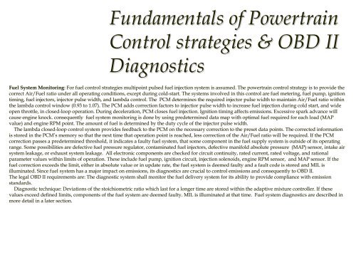
Fundamentals of PowertrainControl strategies & OBD <strong>II</strong><strong>Diagnostics</strong>Fuel System Moni<strong>to</strong>ring: : For fuel control strategies multipoint pulsed fuel injection system sis assumed. The powertrain control strategy is <strong>to</strong> provide thecorrect Air/Fuel ratio under all operating conditions, except during cold-start. The systems involved in this control are fuel metering, fuel fpump, ignitiontiming, fuel injec<strong>to</strong>rs, injec<strong>to</strong>r pulse width, and lambda control. . The PCM determines the required injec<strong>to</strong>r pulse width <strong>to</strong> maintain Air/Fuel ratio withinthe lambda control window (0.93 <strong>to</strong> 1.07). The PCM adds correction n fac<strong>to</strong>rs <strong>to</strong> injectior pulse width <strong>to</strong> increase fuel injection during cold start, and wide wopen throttle, in closed-loop loop operation. During deceleration, PCM closes fuel injection. Ignition timing affects emissions. Excessive spark advance willcause engine knock. consequently fuel system moni<strong>to</strong>ring is done by using predetermined data map with optimal fuel required for each load (MAPvalue) and engine RPM point. The amount of fuel is determined by the duty cycle of the injec<strong>to</strong>r pulse width.The lambda closed-loop loop control system provides feedback <strong>to</strong> the PCM on the necessary y correction <strong>to</strong> the preset data points. The corrected informationis s<strong>to</strong>red in the PCM’s memory so that the next time that operation point is reached, less lcorrection of the Air/Fuel ratio will be required. If the PCMcorrection passes a predetermined threshold, it indicates a faulty fuel system, that some component in the fuel supply system is outside of its operatingrange. Some possibilities are defective fuel pressure regula<strong>to</strong>r, contaminated fuel injec<strong>to</strong>rs, defective manifold absolute pressure (MAP) sensor, intake airsystem leakage, or exhaust system leakage. All electronic components are checked for circuit continuity, rated current, rated voltage, vand rationalparameter values within limits of operation. These include fuel pump, ignition circuit, injection solenoids, engine RPM sensor, and MAP sensor. If thefuel correction exceeds the limit, either in absolute value or in update rate, the fuel system is deemed faulty and a fault code is s<strong>to</strong>red and MIL isilluminated. Since fuel system has a major impact on emissions, its diagnostics are crucial <strong>to</strong> control emissions and consequently y <strong>to</strong> OBD <strong>II</strong>.The legal OBD <strong>II</strong> requirements are: The diagnostic system shall moni<strong>to</strong>r mthe fuel delivery system for its ability <strong>to</strong> provide compliance with emissionstandards.Diagnostic technique: Deviations of the s<strong>to</strong>ichiometric ratio which last for a longer time are s<strong>to</strong>red within the adaptive mixture controller. If thesevalues exceed defined limits, components of the fuel system are deemed faulty. MIL is illuminated at that time. Fuel system diagnostics are described inmore detail in a later section.


