Introduction to On Board Diagnostics (II)
Introduction to On Board Diagnostics (II)
Introduction to On Board Diagnostics (II)

You also want an ePaper? Increase the reach of your titles
YUMPU automatically turns print PDFs into web optimized ePapers that Google loves.
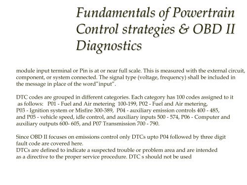
Fundamentals of PowertrainControl strategies & OBD <strong>II</strong><strong>Diagnostics</strong>High Circuit Input: The circuit voltage, frequency or other signal measured at the controlmodule input terminal or Pin is at or near full scale. This is measured with the external circuit,component, or system connected. The signal type (voltage, frequency) shall be included inthe message in place of the word”input”.DTC codes are grouped in different categories. Each category has 100 codes assigned <strong>to</strong> itas follows: P01 - Fuel and Air metering 100-199, P02 - Fuel and Air metering,P03 - Ignition system or Misfire 300-389, P04 - auxiliary emission controls 400 - 485,and P05 - vehicle speed, idle control, and auxiliary inputs 500 - 574, P06 - Computer andauxiliary outputs 600- 605, and P07 Transmission 700 - 790.Since OBD <strong>II</strong> focuses on emissions control only DTCs up<strong>to</strong> P04 followed by three digitfault code are covered here.DTCs are defined <strong>to</strong> indicate a suspected trouble or problem area and are intendedas a directive <strong>to</strong> the proper service procedure. DTC s should not be used <strong>to</strong> indicate theabsence of problems but only <strong>to</strong> indicate specific fault. The decision <strong>to</strong> illuminate MIL forany DTC is manufacture specific based on their testing of how each system malfunctionaffects emissions.