Introduction to On Board Diagnostics (II)
Introduction to On Board Diagnostics (II)
Introduction to On Board Diagnostics (II)
Create successful ePaper yourself
Turn your PDF publications into a flip-book with our unique Google optimized e-Paper software.
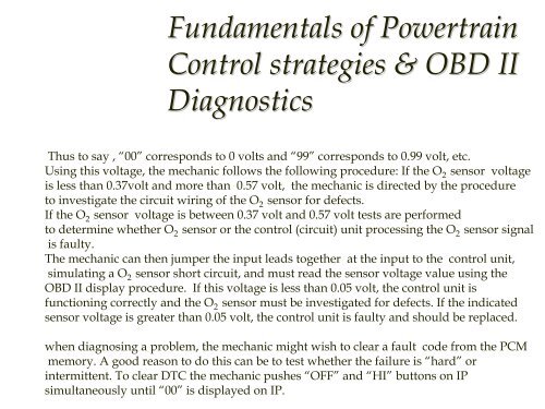
Fundamentals of PowertrainControl strategies & OBD <strong>II</strong><strong>Diagnostics</strong>The desired voltage is displayed on the Instrument panel (IP) in multiples of 1/100 volt.Thus <strong>to</strong> say , “00” corresponds <strong>to</strong> 0 volts and “99” corresponds <strong>to</strong> 0.99 volt, etc.Using this voltage, the mechanic follows the following procedure: If the O sensor 2 voltageis less than 0.37volt and more than 0.57 volt, the mechanic is directed by the procedure<strong>to</strong> investigate the circuit wiring of the O 2 sensor for defects.If the O sensor 2 voltage is between 0.37 volt and 0.57 volt tests are performed<strong>to</strong> determine whether O sensor or the control (circuit) unit processing the O 2 2 sensor signalis faulty.The mechanic can then jumper the input leads <strong>to</strong>gether at the input <strong>to</strong> the control unit,simulating a O 2 sensor short circuit, and must read the sensor voltage value using theOBD <strong>II</strong> display procedure. If this voltage is less than 0.05 volt, the control unit isfunctioning correctly and the O 2 sensor must be investigated for defects. If the indicatedsensor voltage is greater than 0.05 volt, the control unit is faulty and should be replaced.when diagnosing a problem, the mechanic might wish <strong>to</strong> clear a fault code from the PCMmemory. A good reason <strong>to</strong> do this can be <strong>to</strong> test whether the failure is “hard” orintermittent. To clear DTC the mechanic pushes “OFF” and “HI” but<strong>to</strong>ns on IPsimultaneously until “00” is displayed on IP.


