Fundamentals of PowertrainControl strategies & OBD <strong>II</strong><strong>Diagnostics</strong>Secondary Air System Moni<strong>to</strong>ring: Secondary air system is used <strong>to</strong> improve the performance of the catalytic converter (Three way) by providing extraoxygen rich air <strong>to</strong> either the converter itself or <strong>to</strong> the exhaust manifold. The catalyst temperature must be above about 200 o C <strong>to</strong> efficiently oxidize HC andreduce NOx. . During engine warm-up when the catalytic converter is cold, HC and CO are oxidized in the exhaust manifold by routing secondary air <strong>to</strong>the exhaust manifold in controlled quantify by the PCM. This creates extra heat <strong>to</strong> speed warm-up of the converter and EGO sensor, enabling the PCM <strong>to</strong>go in<strong>to</strong> closed-loop loop mode more quickly.During open-loop control (cold converter) the converter is liable <strong>to</strong> be damaged if excessive heat is applied <strong>to</strong> it, <strong>to</strong> warm it up. This can happen ifexcessive amounts of HC and CO are oxidized in the exhaust manifold during periods of heavy loads which call for fuel enrichment, , or during severedeceleration. During start-up and such heavy loads, the secondary air is not let in<strong>to</strong> exhaust manifold but directed in<strong>to</strong> the air cleaner where it has noeffect on exhaust temperatures.After warm-up, during closed-loop loop operation, the secondary air is used <strong>to</strong> supply oxygen <strong>to</strong> the e second chamber of the three-way catalyst, in dual-chamber converter system. In a dual-chamber converter, the first chamber contains rhodium, palladium, , and platinum <strong>to</strong> reduce NOx and <strong>to</strong> oxidize HCand CO. The second chamber contains only platinum and palladium. The extra oxygen from the secondary air improves the converter’s s ability <strong>to</strong> oxidizeHC and CO in the second converter chamber. The control of the secondary air is done by using two solenoid valves similar <strong>to</strong> the EGR pintle valve. <strong>On</strong>evalve switches air flow <strong>to</strong> the exhaust manifold or <strong>to</strong> the air cleaner (atmosphere). The other valve switches air flow <strong>to</strong> the exhaust manifold or <strong>to</strong> thecatalytic converter. The air routing is controlled based on engine ne coolant temperature and Air/Fuel ratio, indicated by the lambda sensor. If the control isopen-loop and if the coolant temperature is below threshold and Air/Fuel ratio is not <strong>to</strong>o rich, then the air flow is directed <strong>to</strong> the exhaust manifold. Ifcoolant temperature is higher than threshold and the Air/Fuel ratio is rich (lambda < 1) then the secondary air is directed <strong>to</strong> the air cleaner which exits<strong>to</strong> the atmosphere. If the control is closed-loop, loop, then the lambda sensor is moni<strong>to</strong>red for correlated deviations when the secondary air flow is changedfrom exhaust manifold, or catalytic converter, or air cleaner, depending don coolant temperature, and lambda value. The OBD <strong>II</strong> requirement is that thesecondary air system shall have the diagnostic system moni<strong>to</strong>r the e proper functioning of the secondary air delivery, and any air switching valve(solenoid).The critical parameters of the secondary air system are moni<strong>to</strong>red d and if found <strong>to</strong> be out of permissible range of values, the fault code is set. The MIL isilluminated.Secondary air diagnostics are described in more detail in a later r section.
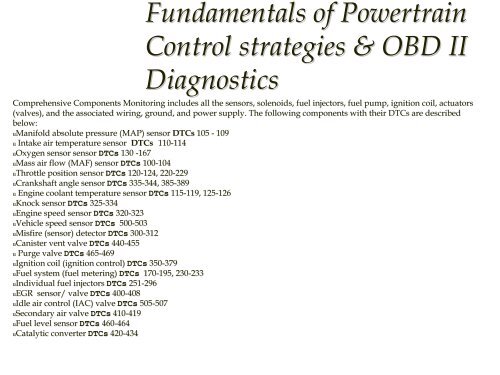
Fundamentals of PowertrainControl strategies & OBD <strong>II</strong><strong>Diagnostics</strong>Comprehensive Components Moni<strong>to</strong>ring includes all the sensors, solenoids, fuel injec<strong>to</strong>rs, fuel pump, ignition coil, actua<strong>to</strong>rs(valves), and the associated wiring, ground, and power supply. The Tfollowing components with their DTCs are describedbelow:uManifold absolute pressure (MAP) sensor DTCs 105 - 109u Intake air temperature sensor DTCs 110-114114uOxygen sensor sensor DTCs 130 -167uMass air flow (MAF) sensor DTCs 100-104104uThrottle position sensor DTCs 120-124, 124, 220-229229uCrankshaft angle sensor DTCs 335-344, 344, 385-389389u Engine coolant temperature sensor DTCs 115-119, 119, 125-126126uKnock sensor DTCs 325-334334uEngine speed sensor DTCs 320-323323uVehicle speed sensor DTCs 500-503503uMisfire (sensor) detec<strong>to</strong>r DTCs 300-312312uCanister vent valve DTCs 440-455455u Purge valve DTCs 465-469469uIgnition coil (ignition control) DTCs 350-379379uFuel system (fuel metering) DTCs 170-195, 195, 230-233233uIndividual fuel injec<strong>to</strong>rs DTCs 251-296296uEGR sensor/ valve DTCs 400-408408uIdle air control (IAC) valve DTCs 505-507507uSecondary air valve DTCs 410-419419uFuel level sensor DTCs 460-464464uCatalytic converter DTCs 420-434434