Section 05: Automatic Tool Changers - FadalCNC.com
Section 05: Automatic Tool Changers - FadalCNC.com
Section 05: Automatic Tool Changers - FadalCNC.com
Create successful ePaper yourself
Turn your PDF publications into a flip-book with our unique Google optimized e-Paper software.
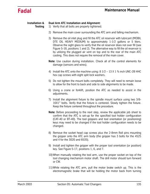
FadalMaintenance ManualInstallation &TestingDual Arm ATC Installation and Alignment:1) Verify that all bolts are properly tightened.2) Remove the main cover surrounding the ATC arm and falling mechanism.3) Remove the oil inlet plug and fill the ATC oil reservoir with lubricant (MOBILDTE OIL HEAVY MEDIUM) to approximately 1-1/2 gallons or 5 liters.Observe the sight glass to verify that the oil reservoir does not over fill (seeFigure 5-18, positions 1 and 2). The alternative way to fill the oil reservoir isby utilizing the plugged air vent on top and to the rear of the main ATCcasting. This does not require the removal of the main cover.Note: Use caution during installation. Check all of the control elements fordamage (sensors and wires).4) Install the ATC onto the machine using: 8 1/2 – 13 X 1 ¾ inch UNC-2B HHChex cap screws with eight split lock washers.5) Do not tighten the mount bolts <strong>com</strong>pletely. They will need to remain looseto allow for the front to back and side to side alignments to be made.6) Using a crane or forklift, position the ATC as needed to assist in theadjustments.7) Install the alignment fixture to the spindle mount surface using two 3/8-16X1” bolts. Verify that the fixture is centered. Slowly tighten the fixture.Keep the fixture centered throughout the procedure.Note: Before proceeding to the next step, review the applicable job sheet toconfirm that the ATC is set-up for the specified tool holder configuration(CAT-40 or BT-40). The tool grippers and tool orientation (or positioning)keys may need to be changed if the tool holder configuration needs to bechanged.8) Remove the socket head cap screws plus the 2-8mm Roll pins mountingthe gripper onto the ATC arm body (the gripper has 3 bolts for the 4525and 4 for the 3020 and 6535).9) Install and tighten the gripper with the proper tool orientation (or position)key. See Figure 5-17, positions 1, 6, and 7.10) When manually rotating the tool arm, use the proper socket on top of thetool changing mechanism motor shaft. The drill motor should turn forwardor CW.11) While rotating the ATC arm, pull the motor brake switch up. This is theelectromagnetic brake that will be holding the motor back from turningMarch 2003 <strong>Section</strong> <strong>05</strong>: <strong>Automatic</strong> <strong>Tool</strong> <strong>Changers</strong> 135


