Section 05: Automatic Tool Changers - FadalCNC.com
Section 05: Automatic Tool Changers - FadalCNC.com
Section 05: Automatic Tool Changers - FadalCNC.com

Create successful ePaper yourself
Turn your PDF publications into a flip-book with our unique Google optimized e-Paper software.
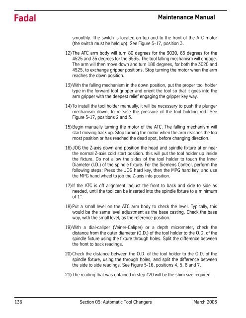
FadalMaintenance Manualsmoothly. The switch is located on top and to the front of the ATC motor(the switch must be held up). See Figure 5-17, position 3.12) The ATC arm body will turn 80 degrees for the 3020, 65 degrees for the4525 and 35 degrees for the 6535. The tool falling mechanism will engage.The arm will then move down and turn 180 degrees, for both the 3020 and4525, to exchange gripper positions. Stop turning the motor when the armreaches the down position.13) With the falling mechanism in the down position, put the proper tool holdertype in the forward tool gripper and orient the tool so that it goes into thearm gripper with the deepest relief engaging the gripper key way.14) To install the tool holder manually, it will be necessary to push the plungermechanism down, to release the pressure of the tool holding rod. SeeFigure 5-17, positions 2 and 3.15) Begin manually turning the motor of the ATC. The falling mechanism willstart moving back up. Stop turning the motor when the arm reaches the topmost position or has reached the dead spot, before changing direction.16) JOG the Z-axis down and position the head and spindle fixture at or nearthe normal Z-axis cold start position. this will put the tool holder up insidethe fixture. Do not allow the sides of the tool holder to touch the InnerDiameter (I.D.) of the spindle fixture. For the Siemens Control, perform thefollowing steps: Press the JOG hard key, then the MPG hard key, and usethe MPG hand wheel to job the Z-axis into position.17) If the ATC is off alignment, adjust the front to back and side to side asneeded, until the tool can be inserted into the spindle fixture to a minimumof 1”.18) Put a small level on the ATC arm body to check the level. Typically, thiswould be the same level adjustment as the base casting. Check the baseway, with the small level, as the reference position.19) With a dial-caliper (Veiner-Caliper) or a depth micrometer, check thedistance from the outer diameter (O.D.) of the tool holder to the O.D. of thespindle fixture using the fixture through holes. Split the difference betweenthe front to back readings.20) Check the distance between the O.D. of the tool holder to the O.D. of thespindle fixture, using the through holes, and split the difference betweenthe side to side readings. See Figure 5-16, positions 4, 5, 6 and 7.21) The reading that was obtained in step #20 will be the shim size required.136 <strong>Section</strong> <strong>05</strong>: <strong>Automatic</strong> <strong>Tool</strong> <strong>Changers</strong> March 2003