computer modeling in molecular biology.pdf
computer modeling in molecular biology.pdf
computer modeling in molecular biology.pdf

You also want an ePaper? Increase the reach of your titles
YUMPU automatically turns print PDFs into web optimized ePapers that Google loves.
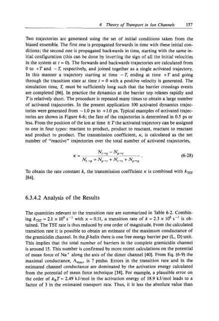
6 Theory of TransDort <strong>in</strong> Zon Channels 157Tho trajectories are generated us<strong>in</strong>g the set of <strong>in</strong>itial conditions taken from thebiased ensemble. The first one is propagated forwards <strong>in</strong> time with these <strong>in</strong>itial conditions;the second one is propagated backwards <strong>in</strong> time, start<strong>in</strong>g with the same <strong>in</strong>itialconfiguration (this can be done by <strong>in</strong>vert<strong>in</strong>g the sign of all the <strong>in</strong>itial velocities<strong>in</strong> the system at t = 0). The forwards and backwards trajectories are calculated from0 to +T and - r respectively, and jo<strong>in</strong>ed together as a s<strong>in</strong>gle activated trajectory.In this manner a trajectory start<strong>in</strong>g at time -r end<strong>in</strong>g at time +T and go<strong>in</strong>gthrough the transition state at time t = 0 with a positive velocity is generated. Thesimulation time, r must be sufficiently long such that the barrier cross<strong>in</strong>gs eventsare completed [86]. In practice the dynamics at the barrier top relaxes rapidly andT is relatively short. The procedure is repeated many times to obta<strong>in</strong> a large numberof activated trajectories. In the present application 100 activated dynamics trajectorieswere generated from - 1.0 ps to + 1.0 ps. Typical examples of activated trajectoriesare shown <strong>in</strong> Figure 6-6; the fate of the trajectories is determ<strong>in</strong>ed <strong>in</strong> 0.5 ps orless. From the position of the ion at time f T the activated trajectory can be assignedto one <strong>in</strong> four types: reactant to product, product to reactant, reactant to reactantand product to product. The transmission coefficient, K, is calculated as the netnumber of “reactive” trajectories over the total number of activated trajectories,To obta<strong>in</strong> the rate constant k, the transmission coefficient K is comb<strong>in</strong>ed with kTsT~41.6.3.4.2 Analysis of the ResultsThe quantities relevant to the transition rate are summarized <strong>in</strong> Table 6-2. Comb<strong>in</strong><strong>in</strong>gkTsT = 2.1 x lo9 s-l with K = 0.11, a transition rate of k = 2.3 X is obta<strong>in</strong>ed.The TST rate is thus reduced by one order of magnitude. From the calculatedtransition rate it is possible to obta<strong>in</strong> an estimate of the maximum conductance ofthe gramicid<strong>in</strong> channel. In the /3-helix there is one free energy barrier per (L, D) unit.This implies that the total number of barriers <strong>in</strong> the complete gramicid<strong>in</strong> channelis around 15. This number is confirmed by more recent calculations on the potentialof mean force of Na+ along the axis of the dimer channel [40]. From Eq. (6-9) themaximal conductance, Amax, is 7 pmho. Errors <strong>in</strong> the transition rate and <strong>in</strong> theestimated channel conductance are dom<strong>in</strong>ated by the activation energy calculatedfrom the potential of mean force technique [38]. For example, a plausible error onthe order of k,T = 2.49 kJ/mol <strong>in</strong> the activation energy of 18.9 kJ/mol leads to afactor of 3 <strong>in</strong> the estimated transport rate. Thus, it is less the absolute value than