3D Visualization and Solid Primitive Conceptual Design in AutoCAD
3D Visualization and Solid Primitive Conceptual Design in AutoCAD
3D Visualization and Solid Primitive Conceptual Design in AutoCAD

You also want an ePaper? Increase the reach of your titles
YUMPU automatically turns print PDFs into web optimized ePapers that Google loves.
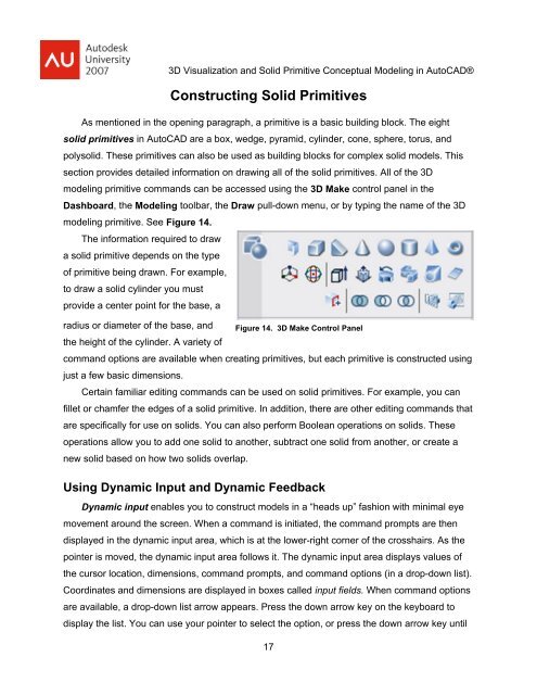
<strong>3D</strong> <strong>Visualization</strong> <strong>and</strong> <strong>Solid</strong> <strong>Primitive</strong> <strong>Conceptual</strong> Model<strong>in</strong>g <strong>in</strong> <strong>AutoCAD</strong>®Construct<strong>in</strong>g <strong>Solid</strong> <strong>Primitive</strong>sAs mentioned <strong>in</strong> the open<strong>in</strong>g paragraph, a primitive is a basic build<strong>in</strong>g block. The eightsolid primitives <strong>in</strong> <strong>AutoCAD</strong> are a box, wedge, pyramid, cyl<strong>in</strong>der, cone, sphere, torus, <strong>and</strong>polysolid. These primitives can also be used as build<strong>in</strong>g blocks for complex solid models. Thissection provides detailed <strong>in</strong>formation on draw<strong>in</strong>g all of the solid primitives. All of the <strong>3D</strong>model<strong>in</strong>g primitive comm<strong>and</strong>s can be accessed us<strong>in</strong>g the <strong>3D</strong> Make control panel <strong>in</strong> theDashboard, the Model<strong>in</strong>g toolbar, the Draw pull-down menu, or by typ<strong>in</strong>g the name of the <strong>3D</strong>model<strong>in</strong>g primitive. See Figure 14.The <strong>in</strong>formation required to drawa solid primitive depends on the typeof primitive be<strong>in</strong>g drawn. For example,to draw a solid cyl<strong>in</strong>der you mustprovide a center po<strong>in</strong>t for the base, aradius or diameter of the base, <strong>and</strong>Figure 14. <strong>3D</strong> Make Control Panelthe height of the cyl<strong>in</strong>der. A variety ofcomm<strong>and</strong> options are available when creat<strong>in</strong>g primitives, but each primitive is constructed us<strong>in</strong>gjust a few basic dimensions.Certa<strong>in</strong> familiar edit<strong>in</strong>g comm<strong>and</strong>s can be used on solid primitives. For example, you canfillet or chamfer the edges of a solid primitive. In addition, there are other edit<strong>in</strong>g comm<strong>and</strong>s thatare specifically for use on solids. You can also perform Boolean operations on solids. Theseoperations allow you to add one solid to another, subtract one solid from another, or create anew solid based on how two solids overlap.Us<strong>in</strong>g Dynamic Input <strong>and</strong> Dynamic FeedbackDynamic <strong>in</strong>put enables you to construct models <strong>in</strong> a “heads up” fashion with m<strong>in</strong>imal eyemovement around the screen. When a comm<strong>and</strong> is <strong>in</strong>itiated, the comm<strong>and</strong> prompts are thendisplayed <strong>in</strong> the dynamic <strong>in</strong>put area, which is at the lower-right corner of the crosshairs. As thepo<strong>in</strong>ter is moved, the dynamic <strong>in</strong>put area follows it. The dynamic <strong>in</strong>put area displays values ofthe cursor location, dimensions, comm<strong>and</strong> prompts, <strong>and</strong> comm<strong>and</strong> options (<strong>in</strong> a drop-down list).Coord<strong>in</strong>ates <strong>and</strong> dimensions are displayed <strong>in</strong> boxes called <strong>in</strong>put fields. When comm<strong>and</strong> optionsare available, a drop-down list arrow appears. Press the down arrow key on the keyboard todisplay the list. You can use your po<strong>in</strong>ter to select the option, or press the down arrow key until17