<strong>3D</strong> <strong>Visualization</strong> <strong>and</strong> <strong>Solid</strong> <strong>Primitive</strong> <strong>Conceptual</strong> Model<strong>in</strong>g <strong>in</strong> <strong>AutoCAD</strong>®EXERCISE #91. Well, I am sure you are do<strong>in</strong>g it already, but go ahead <strong>and</strong> use the grips <strong>and</strong> startmodify<strong>in</strong>g your solids primitives from the previous exercise.Overview of Subobject Edit<strong>in</strong>g<strong>AutoCAD</strong> solid primitives, such as cyl<strong>in</strong>ders, wedges, <strong>and</strong> boxes, are composed of threetypes of subobjects: faces, edges, <strong>and</strong> vertices. In addition, the objects that are used withBoolean comm<strong>and</strong>s to create a composite solid are considered subobjects, if the history isrecorded. The primitive subobjects can be edited. Once selected, the primitive subobjects caneven be deleted from the composite solid.Subobjects can be easily edited us<strong>in</strong>g grips, which provide an <strong>in</strong>tuitive <strong>and</strong> flexible methodof solid model design. For example, suppose you need to rotate a face subobject <strong>in</strong> the currentXY plane. You can select the subobject, pick its base grip, <strong>and</strong> then cycle through the edit<strong>in</strong>gfunctions to ROTATE. You can also use the ROTATE comm<strong>and</strong> on the selected subobject.Select<strong>in</strong>g SubobjectsTo select a subobject, press the [Ctrl] key <strong>and</strong> pick the subobject. You can select multiplesubobjects <strong>and</strong> subobjects on multiple objects. To select a subobject that is hidden <strong>in</strong> thecurrent view, first display the model as a wireframe. After creat<strong>in</strong>g a selection set, select a grip<strong>and</strong> edit the subobject as needed. Multiple objects can be selected <strong>in</strong> this manner. To deselectobjects, press the [Shift]+[Ctrl] key comb<strong>in</strong>ation <strong>and</strong> pick the objects to be removed from theselection set.If objects or subobjects are overlapp<strong>in</strong>g, press the [Ctrl] key <strong>and</strong> the spacebar to turn oncycl<strong>in</strong>g <strong>and</strong> pick the subobject. Then, release the spacebar, cont<strong>in</strong>ue hold<strong>in</strong>g the [Ctrl] key, <strong>and</strong>pick until the subobject you need is highlighted. Press [Enter] or the spacebar to select thehighlighted subobject.The [Ctrl] key method can be used to select subobjects for use with edit<strong>in</strong>g comm<strong>and</strong>s suchas MOVE, COPY, ROTATE, SCALE, ARRAY, <strong>and</strong> ERASE. Some comm<strong>and</strong>s, like ARRAY,STRETCH, <strong>and</strong> MIRROR, are applied to the entire solid. Other operations may not be applied atall, depend<strong>in</strong>g on which type of subobject is selected. You can also use the Properties w<strong>in</strong>dow30
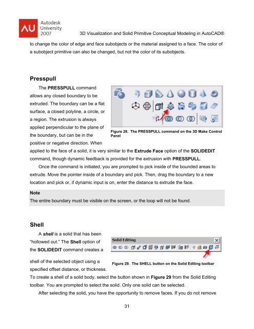
<strong>3D</strong> <strong>Visualization</strong> <strong>and</strong> <strong>Solid</strong> <strong>Primitive</strong> <strong>Conceptual</strong> Model<strong>in</strong>g <strong>in</strong> <strong>AutoCAD</strong>®to change the color of edge <strong>and</strong> face subobjects or the material assigned to a face. The color ofa subobject primitive can also be changed, but not the color of its subobjects.PresspullThe PRESSPULL comm<strong>and</strong>allows any closed boundary to beextruded. The boundary can be a flatsurface, a closed polyl<strong>in</strong>e, a circle, ora region. The extrusion is alwaysapplied perpendicular to the plane ofFigure 28. The PRESSPULL comm<strong>and</strong> on the <strong>3D</strong> Make Controlthe boundary, but can be <strong>in</strong> the Panelpositive or negative direction. Whenapplied to the face of a solid, it is very similar to the Extrude Face option of the SOLIDEDITcomm<strong>and</strong>, though dynamic feedback is provided for the extrusion with PRESSPULL.Once the comm<strong>and</strong> is <strong>in</strong>itiated, you are prompted to pick <strong>in</strong>side of the bounded areas toextrude. Move the po<strong>in</strong>ter <strong>in</strong>side of a boundary <strong>and</strong> pick. Then, drag the boundary to a newlocation <strong>and</strong> pick or, if dynamic <strong>in</strong>put is on, enter the distance to extrude the face.NoteThe entire boundary must be visible on the screen, or the loop will not be found.ShellA shell is a solid that has been“hollowed out.” The Shell option ofthe SOLIDEDIT comm<strong>and</strong> creates ashell of the selected object us<strong>in</strong>g aFigure 29. The SHELL button on the <strong>Solid</strong> Edit<strong>in</strong>g toolbarspecified offset distance, or thickness.To create a shell of a solid body, select the button shown <strong>in</strong> Figure 29 from the <strong>Solid</strong> Edit<strong>in</strong>gtoolbar. You are prompted to select the solid. Only one solid can be selected.After select<strong>in</strong>g the solid, you have the opportunity to remove faces. If you do not remove31