<strong>3D</strong> <strong>Visualization</strong> <strong>and</strong> <strong>Solid</strong> <strong>Primitive</strong> <strong>Conceptual</strong> Model<strong>in</strong>g <strong>in</strong> <strong>AutoCAD</strong>®Grip Edit<strong>in</strong>g <strong>Solid</strong> <strong>Primitive</strong>sThere are three basic types of <strong>3D</strong> solids <strong>in</strong> <strong>AutoCAD</strong>. The comm<strong>and</strong>s BOX, WEDGE,CYLINDER, SPHERE, etc., create <strong>3D</strong> solid primitives. Sweeps are 2D profiles given thicknessby the EXTRUDE, REVOLVE, SWEEP, <strong>and</strong> LOFT comm<strong>and</strong>s to create a <strong>3D</strong> solid. F<strong>in</strong>ally, <strong>3D</strong>solid composites are created by a Boolean operation or by us<strong>in</strong>g the SOLIDEDIT comm<strong>and</strong>.There are two types of grips—base <strong>and</strong> parameter—that may be associated with a solid object.These grips provide an <strong>in</strong>tuitive means of modify<strong>in</strong>g solids. Base grips are square <strong>and</strong>parameter grips are typically arrows. The edit<strong>in</strong>g that can be performed with these grips arediscussed <strong>in</strong> the next sections. The <strong>3D</strong> solid primitives (box, wedge, pyramid, cyl<strong>in</strong>der, cone,sphere, <strong>and</strong> torus) all have basically the same grips. However, not all grips are available on allprimitives. All primitives have a base grip at the centroid of the base. This grip functions like ast<strong>and</strong>ard grip <strong>in</strong> 2D work. It can be used to stretch, move, rotate, scale, or mirror thesolid.Boxes, wedges, <strong>and</strong> pyramids have square base grips at the corners that allow the size ofthe base to be changed. See Figure 24. Select one of these grips, move the cursor, <strong>and</strong> selectFigure 24. Grips as shown on a Box, Wedge, <strong>and</strong> Pyramida new po<strong>in</strong>t. The object dynamically changes <strong>in</strong> the viewport as you move the grip. You can alsotype the new coord<strong>in</strong>ate location for the grip <strong>and</strong> press [Enter]. If ortho is off, the length <strong>and</strong>width can be changed at the same time by dragg<strong>in</strong>g the grip, except <strong>in</strong> the case of a pyramid.The parameter grips on the base allow the length or width to be changed. Additionally, theheight of these objects can be changed us<strong>in</strong>g parameter grips. Each object has one parameter28
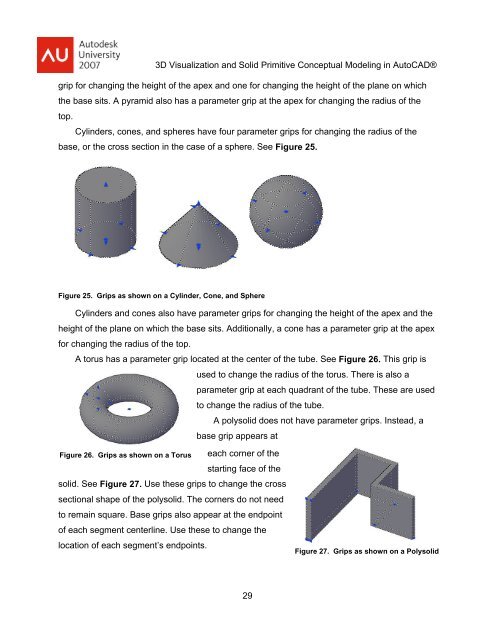
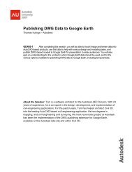
<strong>3D</strong> <strong>Visualization</strong> <strong>and</strong> <strong>Solid</strong> <strong>Primitive</strong> <strong>Conceptual</strong> Model<strong>in</strong>g <strong>in</strong> <strong>AutoCAD</strong>®grip for chang<strong>in</strong>g the height of the apex <strong>and</strong> one for chang<strong>in</strong>g the height of the plane on whichthe base sits. A pyramid also has a parameter grip at the apex for chang<strong>in</strong>g the radius of thetop.Cyl<strong>in</strong>ders, cones, <strong>and</strong> spheres have four parameter grips for chang<strong>in</strong>g the radius of thebase, or the cross section <strong>in</strong> the case of a sphere. See Figure 25.Figure 25. Grips as shown on a Cyl<strong>in</strong>der, Cone, <strong>and</strong> SphereCyl<strong>in</strong>ders <strong>and</strong> cones also have parameter grips for chang<strong>in</strong>g the height of the apex <strong>and</strong> theheight of the plane on which the base sits. Additionally, a cone has a parameter grip at the apexfor chang<strong>in</strong>g the radius of the top.A torus has a parameter grip located at the center of the tube. See Figure 26. This grip isused to change the radius of the torus. There is also aparameter grip at each quadrant of the tube. These are usedto change the radius of the tube.A polysolid does not have parameter grips. Instead, abase grip appears atFigure 26. Grips as shown on a Torus each corner of thestart<strong>in</strong>g face of thesolid. See Figure 27. Use these grips to change the crosssectional shape of the polysolid. The corners do not needto rema<strong>in</strong> square. Base grips also appear at the endpo<strong>in</strong>tof each segment centerl<strong>in</strong>e. Use these to change thelocation of each segment’s endpo<strong>in</strong>ts.Figure 27. Grips as shown on a Polysolid29