3D Visualization and Solid Primitive Conceptual Design in AutoCAD
3D Visualization and Solid Primitive Conceptual Design in AutoCAD
3D Visualization and Solid Primitive Conceptual Design in AutoCAD

You also want an ePaper? Increase the reach of your titles
YUMPU automatically turns print PDFs into web optimized ePapers that Google loves.
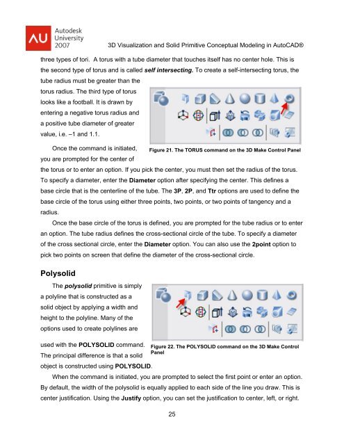
<strong>3D</strong> <strong>Visualization</strong> <strong>and</strong> <strong>Solid</strong> <strong>Primitive</strong> <strong>Conceptual</strong> Model<strong>in</strong>g <strong>in</strong> <strong>AutoCAD</strong>®three types of tori. A torus with a tube diameter that touches itself has no center hole. This isthe second type of torus <strong>and</strong> is called self <strong>in</strong>tersect<strong>in</strong>g. To create a self-<strong>in</strong>tersect<strong>in</strong>g torus, thetube radius must be greater than thetorus radius. The third type of toruslooks like a football. It is drawn byenter<strong>in</strong>g a negative torus radius <strong>and</strong>a positive tube diameter of greatervalue, i.e. –1 <strong>and</strong> 1.1.Once the comm<strong>and</strong> is <strong>in</strong>itiated, Figure 21. The TORUS comm<strong>and</strong> on the <strong>3D</strong> Make Control Panelyou are prompted for the center ofthe torus or to enter an option. If you pick the center, you must then set the radius of the torus.To specify a diameter, enter the Diameter option after specify<strong>in</strong>g the center. This def<strong>in</strong>es abase circle that is the centerl<strong>in</strong>e of the tube. The 3P, 2P, <strong>and</strong> Ttr options are used to def<strong>in</strong>e thebase circle of the torus us<strong>in</strong>g either three po<strong>in</strong>ts, two po<strong>in</strong>ts, or two po<strong>in</strong>ts of tangency <strong>and</strong> aradius.Once the base circle of the torus is def<strong>in</strong>ed, you are prompted for the tube radius or to enteran option. The tube radius def<strong>in</strong>es the cross-sectional circle of the tube. To specify a diameterof the cross sectional circle, enter the Diameter option. You can also use the 2po<strong>in</strong>t option topick two po<strong>in</strong>ts on screen that def<strong>in</strong>e the diameter of the cross-sectional circle.PolysolidThe polysolid primitive is simplya polyl<strong>in</strong>e that is constructed as asolid object by apply<strong>in</strong>g a width <strong>and</strong>height to the polyl<strong>in</strong>e. Many of theoptions used to create polyl<strong>in</strong>es areused with the POLYSOLID comm<strong>and</strong>. Figure 22. The POLYSOLID comm<strong>and</strong> on the <strong>3D</strong> Make ControlPanelThe pr<strong>in</strong>cipal difference is that a solidobject is constructed us<strong>in</strong>g POLYSOLID.When the comm<strong>and</strong> is <strong>in</strong>itiated, you are prompted to select the first po<strong>in</strong>t or enter an option.By default, the width of the polysolid is equally applied to each side of the l<strong>in</strong>e you draw. This iscenter justification. Us<strong>in</strong>g the Justify option, you can set the justification to center, left, or right.25