

Image Acquisitionand Proces

You also want an ePaper? Increase the reach of your titles
YUMPU automatically turns print PDFs into web optimized ePapers that Google loves.
Displaying <strong>Image</strong>s 83<br />
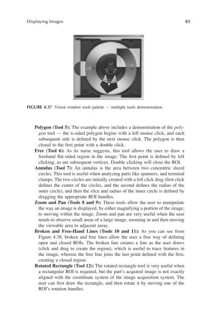
FIGURE 4.37 Vision window tools palette — multiple tools demonstration.<br />
Polygon (Tool 5): The example above includes a demonstration of the polygon<br />
tool — the n-sided polygon begins with a left mouse click, and each<br />
subsequent side is deÞned by the next mouse click. The polygon is then<br />
closed to the Þrst point with a double click.<br />
Free (Tool 6): As its name suggests, this tool allows the user to draw a<br />
freehand ßat-sided region in the image. The Þrst point is deÞned by left<br />
clicking, as are subsequent vertices. Double clicking will close the ROI.<br />
Annulus (Tool 7): An annulus is the area between two concentric sliced<br />
circles. This tool is useful when analyzing parts like spanners, and terminal<br />
clamps. The two circles are initially created with a left click drag (Þrst click<br />
deÞnes the center of the circles, and the second deÞnes the radius of the<br />
outer circle), and then the slice and radius of the inner circle is deÞned by<br />
dragging the appropriate ROI handles.<br />
Zoom and Pan (Tools 8 and 9): These tools allow the user to manipulate<br />
the way an image is displayed, by either magnifying a portion of the image,<br />
to moving within the image. Zoom and pan are very useful when the user<br />
needs to observe small areas of a large image, zooming in and then moving<br />
the viewable area to adjacent areas.<br />
Broken and Free-Hand Lines (Tools 10 and 11): As you can see from<br />
Figure 4.38, broken and free lines allow the user a free way of deÞning<br />
open and closed ROIs. The broken line creates a line as the user draws<br />
(click and drag to create the region), which is useful to trace features in<br />
the image, whereas the free line joins the last point deÞned with the Þrst,<br />
creating a closed region.<br />
Rotated Rectangle (Tool 12): The rotated rectangle tool is very useful when<br />
a rectangular ROI is required, but the part’s acquired image is not exactly<br />
aligned with the coordinate system of the image acquisition system. The<br />
user can Þrst draw the rectangle, and then rotate it by moving one of the<br />
ROI’s rotation handles.