

Final report for WP4.3: Enhancement of design methods ... - Upwind
Final report for WP4.3: Enhancement of design methods ... - Upwind
Final report for WP4.3: Enhancement of design methods ... - Upwind

Create successful ePaper yourself
Turn your PDF publications into a flip-book with our unique Google optimized e-Paper software.
UPWIND WP4: Offshore Support Structures and Foundations<br />
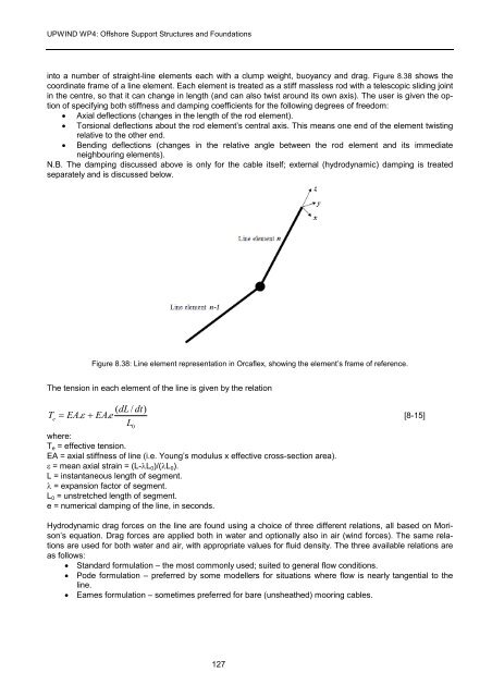
into a number <strong>of</strong> straight-line elements each with a clump weight, buoyancy and drag. Figure 8.38 shows the<br />
coordinate frame <strong>of</strong> a line element. Each element is treated as a stiff massless rod with a telescopic sliding joint<br />
in the centre, so that it can change in length (and can also twist around its own axis). The user is given the option<br />
<strong>of</strong> specifying both stiffness and damping coefficients <strong>for</strong> the following degrees <strong>of</strong> freedom:<br />
• Axial deflections (changes in the length <strong>of</strong> the rod element).<br />
• Torsional deflections about the rod element’s central axis. This means one end <strong>of</strong> the element twisting<br />
relative to the other end.<br />
• Bending deflections (changes in the relative angle between the rod element and its immediate<br />
neighbouring elements).<br />
N.B. The damping discussed above is only <strong>for</strong> the cable itself; external (hydrodynamic) damping is treated<br />
separately and is discussed below.<br />
Figure 8.38: Line element representation in Orcaflex, showing the element’s frame <strong>of</strong> reference.<br />
The tension in each element <strong>of</strong> the line is given by the relation<br />
T e<br />
( dL / dt)<br />
= EA.<br />
ε + EA.<br />
e<br />
[8-15]<br />
L<br />
where:<br />
0<br />
Te = effective tension.<br />
EA = axial stiffness <strong>of</strong> line (i.e. Young’s modulus x effective cross-section area).<br />
ε = mean axial strain = (L-λL0)/(λL0).<br />
L = instantaneous length <strong>of</strong> segment.<br />
λ = expansion factor <strong>of</strong> segment.<br />
L0 = unstretched length <strong>of</strong> segment.<br />
e = numerical damping <strong>of</strong> the line, in seconds.<br />
Hydrodynamic drag <strong>for</strong>ces on the line are found using a choice <strong>of</strong> three different relations, all based on Morison’s<br />
equation. Drag <strong>for</strong>ces are applied both in water and optionally also in air (wind <strong>for</strong>ces). The same relations<br />
are used <strong>for</strong> both water and air, with appropriate values <strong>for</strong> fluid density. The three available relations are<br />
as follows:<br />
• Standard <strong>for</strong>mulation – the most commonly used; suited to general flow conditions.<br />
• Pode <strong>for</strong>mulation – preferred by some modellers <strong>for</strong> situations where flow is nearly tangential to the<br />
line.<br />
• Eames <strong>for</strong>mulation – sometimes preferred <strong>for</strong> bare (unsheathed) mooring cables.<br />
127


