

Final report for WP4.3: Enhancement of design methods ... - Upwind
Final report for WP4.3: Enhancement of design methods ... - Upwind
Final report for WP4.3: Enhancement of design methods ... - Upwind

You also want an ePaper? Increase the reach of your titles
YUMPU automatically turns print PDFs into web optimized ePapers that Google loves.
Table 5.28: Output locations <strong>for</strong> damage equivalent loads<br />
Jacket location Bladed identifier Load component<br />
Mbr 1 End 1 Axial <strong>for</strong>ce Fx<br />
Pile head<br />
Mbr 2 End 1<br />
Mbr 3 End 1<br />
Axial <strong>for</strong>ce Fx<br />
Axial <strong>for</strong>ce Fx<br />
Mbr 4 End 1 Axial <strong>for</strong>ce Fx<br />
Mbr 109 End 1 Axial <strong>for</strong>ce Fx<br />
Upper joint<br />
Mbr 110 End 1<br />
Mbr 111 End 1<br />
Axial <strong>for</strong>ce Fx<br />
Axial <strong>for</strong>ce Fx<br />
Mbr 112 End 1 Axial <strong>for</strong>ce Fx<br />
Tower base Mbr 134 End 1 Overturning bending moment Mz<br />
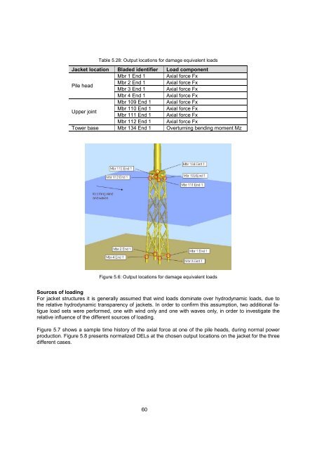
Figure 5.6: Output locations <strong>for</strong> damage equivalent loads<br />
Sources <strong>of</strong> loading<br />
For jacket structures it is generally assumed that wind loads dominate over hydrodynamic loads, due to<br />
the relative hydrodynamic transparency <strong>of</strong> jackets. In order to confirm this assumption, two additional fatigue<br />
load sets were per<strong>for</strong>med, one with wind only and one with waves only, in order to investigate the<br />
relative influence <strong>of</strong> the different sources <strong>of</strong> loading.<br />
Figure 5.7 shows a sample time history <strong>of</strong> the axial <strong>for</strong>ce at one <strong>of</strong> the pile heads, during normal power<br />
production. Figure 5.8 presents normalized DELs at the chosen output locations on the jacket <strong>for</strong> the three<br />
different cases.<br />
60


