MICROSCAN User Manual - Snap-on
MICROSCAN User Manual - Snap-on
MICROSCAN User Manual - Snap-on

Create successful ePaper yourself
Turn your PDF publications into a flip-book with our unique Google optimized e-Paper software.
Data Parameters L<strong>on</strong>g Parameter Names<br />
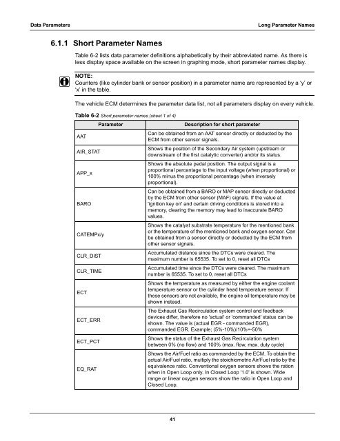
6.1.1 Short Parameter Names<br />
Table 6-2 lists data parameter definiti<strong>on</strong>s alphabetically by their abbreviated name. As there is<br />
less display space available <strong>on</strong> the screen in graphing mode, short parameter names display.<br />
NOTE:<br />
i Counters (like cylinder bank or sensor positi<strong>on</strong>) in a parameter name are represented by a ‘y’ or<br />
‘x’ in the table.<br />
The vehicle ECM determines the parameter data list, not all parameters display <strong>on</strong> every vehicle.<br />
Table 6-2 Short parameter names (sheet 1 of 4)<br />
Parameter Descripti<strong>on</strong> for short parameter<br />
AAT<br />
Can be obtained from an AAT sensor directly or deducted by the<br />
ECM from other sensor signals.<br />
AIR_STAT<br />
APP_x<br />
BARO<br />
CATEMPx/y<br />
CLR_DIST<br />
CLR_TIME<br />
ECT<br />
ECT_ERR<br />
ECT_PCT<br />
EQ_RAT<br />
Shows the positi<strong>on</strong> of the Sec<strong>on</strong>dary Air system (upstream or<br />
downstream of the first catalytic c<strong>on</strong>verter) and/or its status.<br />
Shows the absolute pedal positi<strong>on</strong>. The output signal is a<br />
proporti<strong>on</strong>al percentage to the input voltage (when proporti<strong>on</strong>al) or<br />
100% minus the proporti<strong>on</strong>al percentage (when inversely<br />
proporti<strong>on</strong>al).<br />
Can be obtained from a BARO or MAP sensor directly or deducted<br />
by the ECM from other sensor (MAF) signals. If the value at<br />
'igniti<strong>on</strong> key <strong>on</strong>' and certain driving c<strong>on</strong>diti<strong>on</strong>s is stored into a<br />
memory, clearing the memory may lead to inaccurate BARO<br />
values.<br />
Shows the catalyst substrate temperature for the menti<strong>on</strong>ed bank<br />
or the temperature of the menti<strong>on</strong>ed bank and oxygen sensor. Can<br />
be obtained from a sensor directly or deducted by the ECM from<br />
other sensor signals.<br />
Accumulated distance since the DTCs were cleared. The<br />
maximum number is 65535. To set to 0, reset all DTCs<br />
Accumulated time since the DTCs were cleared. The maximum<br />
number is 65535. To set to 0, reset all DTCs<br />
Shows the temperature as measured by either the engine coolant<br />
temperature sensor or the cylinder head temperature sensor. If<br />
these sensors are not available, the engine oil temperature may be<br />
shown instead.<br />
The Exhaust Gas Recirculati<strong>on</strong> system c<strong>on</strong>trol and feedback<br />
devices differ, therefore no 'actual' or 'commanded' status can be<br />
shown. The value is (actual EGR - commanded EGR),<br />
commanded EGR. Example; (5%-10%)/10%=-50%<br />
Shows the status of the Exhaust Gas Recirculati<strong>on</strong> system<br />
between 0% (no flow) and 100% (max. flow, max. duty cycle)<br />
Shows the Air/Fuel ratio as commanded by the ECM. To obtain the<br />
actual Air/Fuel ratio, multiply the stoichiometric Air/Fuel ratio by the<br />
equivalence ratio. C<strong>on</strong>venti<strong>on</strong>al oxygen sensors shows the rati<strong>on</strong><br />
when in Open Loop <strong>on</strong>ly. In Closed Loop '1.0' is shown. Wide<br />
range or linear oxygen sensors show the ratio in Open Loop and<br />
Closed Loop.<br />
41