MICROSCAN User Manual - Snap-on
MICROSCAN User Manual - Snap-on
MICROSCAN User Manual - Snap-on

Create successful ePaper yourself
Turn your PDF publications into a flip-book with our unique Google optimized e-Paper software.
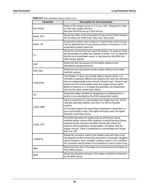
Data Parameters L<strong>on</strong>g Parameter Names<br />
Table 6-2 Short parameter names (sheet 2 of 4)<br />
EQ_RATxy<br />
EVAP_PCT<br />
EVAP_VP<br />
FLI<br />
FRP<br />
FRP_REL<br />
FUELSYSx<br />
IAT<br />
LOAD_ABS<br />
LOAD_PCT<br />
LONGFTx<br />
MAF<br />
MAP<br />
Parameter Descripti<strong>on</strong> for short parameter<br />
Status of the oxygen sensor in V or as a ratio. Designed for linear<br />
or wide-ratio oxygen sensors.<br />
See also PID $14 and up or $34 and up.<br />
Shows the status of the Evaporative Purge C<strong>on</strong>trol Valve between<br />
0% (no flow) and 100% (max. flow, max. duty cycle)<br />
Evaporative system vapor pressure, if used by the c<strong>on</strong>trol module.<br />
Can be obtained from a fuel pressure sensor in the tank or in the<br />
evaporative system vapor line.<br />
Shows the nominal fuel tank liquid fill capacity. For gaseous fuels<br />
the percentage of usable fuel capacity is shown. Can be obtained<br />
directly from a dedicated sensor or calculated by the ECM from<br />
other sensor signals.<br />
Shows the fuel rail pressure at the engine relative to the<br />
atmosphere (gauge pressure).<br />
Shows the fuel rail pressure at the engine relative to the intake<br />
manifold vacuum.<br />
Fuel System 'x' does not normally refer to injector banks. It is<br />
intended to represent different fuel systems (for multi-fuel vehicles)<br />
that can independently enter and exit 'Closed Loop'. 'Closed Loop'<br />
means the fuel c<strong>on</strong>trol system uses the oxygen sensor signal.<br />
Banks of injectors <strong>on</strong> a V-engine are generally not independent<br />
and use the same closed loop criteria.<br />
Shows the intake manifold air temperature as obtained from a<br />
sensor or as calculated by the ECM (using other inputs).<br />
Value is presented as a percentage and ranges from 0 to 100 for<br />
naturally aspirated engines, and from 0 to 400 for boosted<br />
engines.<br />
On boosted engines the actual figure displayed is dependant <strong>on</strong><br />
how much boost is used. The higher the boost used, the higher<br />
Absolute Load Value will be.<br />
The ECM calculates the engine load by dividing the actual<br />
manifold airflow volume (Otto engines) or actual fuel flow (Diesel<br />
engines) by the maximum possible volume with a factor for<br />
pressure and temperature compensati<strong>on</strong>. Correlates with the<br />
engine vacuum. Value is presented as a percentage and ranges<br />
from 0 to 100.<br />
Shows the correcti<strong>on</strong> used by the Closed Loop and Open Loop<br />
fuel algorithm at the moment this parameter is requested. Negative<br />
values indicate a 'lean' c<strong>on</strong>diti<strong>on</strong>, positive values a 'rich' c<strong>on</strong>diti<strong>on</strong>.<br />
0% correcti<strong>on</strong> will be shown if no correcti<strong>on</strong> is used in Open Loop.<br />
Shows the flow rate of the intake air as measured by the Mass Air<br />
Flow (MAF) sensor.<br />
Shows the absolute pressure in the intake manifold as measured<br />
by the MAP sensor.<br />
42