HP StorageWorks 4400 Enterprise Virtual Array user ... - BUSINESS IT
HP StorageWorks 4400 Enterprise Virtual Array user ... - BUSINESS IT
HP StorageWorks 4400 Enterprise Virtual Array user ... - BUSINESS IT

You also want an ePaper? Increase the reach of your titles
YUMPU automatically turns print PDFs into web optimized ePapers that Google loves.
PDU 1<br />
PDU 2<br />
PDMs<br />
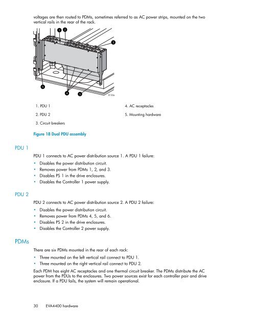
voltages are then routed to PDMs, sometimes referred to as AC power strips, mounted on the two<br />
vertical rails in the rear of the rack.<br />
5<br />
1. PDU 1<br />
2. PDU 2<br />
1<br />
3. Circuit breakers<br />
2<br />
4 5<br />
Figure 18 Dual PDU assembly<br />
3<br />
0130a<br />
4. AC receptacles<br />
5. Mounting hardware<br />
PDU 1 connects to AC power distribution source 1. A PDU 1 failure:<br />
Disables the power distribution circuit.<br />
Removes power from PDMs 1, 2, and 3.<br />
Disables PS 1 in the drive enclosures.<br />
Disables the Controller 1 power supply.<br />
PDU 2 connects to AC power distribution source 2. A PDU 2 failure:<br />
Disables the power distribution circuit.<br />
Removes power from PDMs 4, 5, and 6.<br />
Disables PS 2 in the drive enclosures.<br />
Disables the Controller 2 power supply.<br />
There are six PDMs mounted in the rear of each rack:<br />
Three mounted on the left vertical rail connect to PDU 1.<br />
Three mounted on the right vertical rail connect to PDU 2.<br />
Each PDM has eight AC receptacles and one thermal circuit breaker. The PDMs distribute the AC<br />
power from the PDUs to the enclosures. Two power sources exist for each controller pair and drive<br />
enclosure. If a PDU fails, the system will remain operational.<br />
30<br />
EVA<strong>4400</strong> hardware