reverse engineering – recent advances and applications - OpenLibra
reverse engineering – recent advances and applications - OpenLibra
reverse engineering – recent advances and applications - OpenLibra

You also want an ePaper? Increase the reach of your titles
YUMPU automatically turns print PDFs into web optimized ePapers that Google loves.
140<br />
Reverse Engineering <strong>–</strong> Recent Advances <strong>and</strong> Applications<br />
tolerancing systems are not fully compatible, they both define position geometrical tolerance<br />
as the total permissible variation in the location of a feature about its exact true position. For<br />
cylindrical features such as holes or bosses the position tolerance zone is usually the<br />
diameter of the cylinder within which the axis of the feature must lie, the center of the<br />
tolerance zone being at the exact true position, Figure 2, whereas for size features such as<br />
slots or tabs, it is the total width of the tolerance zone within which the center plane of the<br />
feature must lie, the center plane of the zone being at the exact true position. The position<br />
tolerance of a feature is denoted with the size of the diameter of the cylindrical tolerance<br />
zone (or the distance between the parallel planes of the tolerance zone) in conjunction with<br />
the theoretically exact dimensions that determine the true position <strong>and</strong> their relevant<br />
datums, Figure 2. Datums are, consequently, fundamental building blocks of a positional<br />
tolerance frame in positional tolerancing. Datum features are chosen to position the<br />
toleranced feature in relation to a Cartesian system of three mutually perpendicular planes,<br />
jointly called Datum Reference Frame (DRF), <strong>and</strong> restrict its motion in relation to it.<br />
Positional tolerances often require a three plane datum system, named as primary,<br />
secondary <strong>and</strong> tertiary datum planes. The required number of datums (1, 2 or 3) is derived<br />
by considering the degrees of freedom of the toleranced feature that need to be restricted.<br />
Change of the datums <strong>and</strong>/or their order of precedence in the DRF results to different<br />
geometrical accuracies, (Kaisarlis et al., 2008).<br />
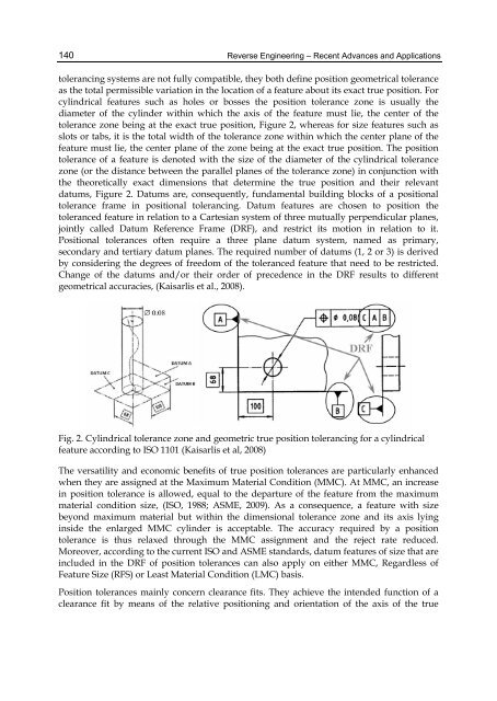
Fig. 2. Cylindrical tolerance zone <strong>and</strong> geometric true position tolerancing for a cylindrical<br />
feature according to ISO 1101 (Kaisarlis et al, 2008)<br />
The versatility <strong>and</strong> economic benefits of true position tolerances are particularly enhanced<br />
when they are assigned at the Maximum Material Condition (MMC). At MMC, an increase<br />
in position tolerance is allowed, equal to the departure of the feature from the maximum<br />
material condition size, (ISO, 1988; ASME, 2009). As a consequence, a feature with size<br />
beyond maximum material but within the dimensional tolerance zone <strong>and</strong> its axis lying<br />
inside the enlarged MMC cylinder is acceptable. The accuracy required by a position<br />
tolerance is thus relaxed through the MMC assignment <strong>and</strong> the reject rate reduced.<br />
Moreover, according to the current ISO <strong>and</strong> ASME st<strong>and</strong>ards, datum features of size that are<br />
included in the DRF of position tolerances can also apply on either MMC, Regardless of<br />
Feature Size (RFS) or Least Material Condition (LMC) basis.<br />
Position tolerances mainly concern clearance fits. They achieve the intended function of a<br />
clearance fit by means of the relative positioning <strong>and</strong> orientation of the axis of the true