reverse engineering – recent advances and applications - OpenLibra
reverse engineering – recent advances and applications - OpenLibra
reverse engineering – recent advances and applications - OpenLibra

You also want an ePaper? Increase the reach of your titles
YUMPU automatically turns print PDFs into web optimized ePapers that Google loves.
A Review on Shape Engineering <strong>and</strong> Design Parameterization in Reverse Engineering<br />
sketch generated are non-planar spline curves that cannot be parameterized. Users can use<br />
either or both methods to generate solid features for a single part.<br />
Method 1: Sketch<br />
In general, there are six steps employed in using the sketch method, (1) creating reference<br />
sketch plane, (2) extracting sketch profile by intersecting the sketch plane with the polygon<br />
mesh, (3) converting extracted geometric entities (usually as planar spline curves) into<br />
regular line entities, such as arcs <strong>and</strong> straight lines, (4) parameterizing the sketch by adding<br />
dimensions <strong>and</strong> constraints, (5) extruding, revolving, or lofting the sketches to create solid<br />
features; <strong>and</strong> (6) employing Boolean operations to union, subtract, or intersect features if<br />
necessary.<br />
Rapidform provides Auto Sketch capability that automatically converts extracted spline curves<br />
into lines, circles, arcs, <strong>and</strong> rectangles, with some constraints added. Most constraints <strong>and</strong><br />
dimensions will have to be added interactively to fully parameterize the sketch profile.<br />
Steps 4 to 6 are similar to conventional CAD operations. With capabilities offered by<br />
Rapidform, fully constrained parametric solid models can be created efficiently.<br />
For the block example, a plane that is parallel to the top (or bottom) face of the base block<br />
was created first (by simply clicking more than three points on the surface). The plane is<br />
offset vertically to ensure a proper intersection between the sketch plane <strong>and</strong> the polygon<br />
mesh. The geometric entities obtained from the intersection are planar spline curves. The<br />
Auto Sketch capability of Rapidform can be used to extract a set of regular CAD-like line<br />
entities that best fit the spline curves. These st<strong>and</strong>ard line entities can be joined <strong>and</strong><br />
parameterized by manually adding dimensions <strong>and</strong> constraints for a fully parameterized<br />
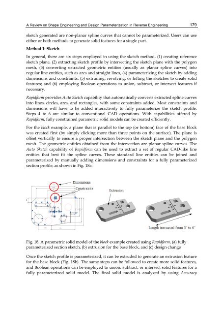
section profile, as shown in Fig. 18a.<br />
Fig. 18. A parametric solid model of the block example created using Rapidform, (a) fully<br />
parameterized section sketch, (b) extrusion for the base block, <strong>and</strong> (c) design change<br />
Once the sketch profile is parameterized, it can be extruded to generate an extrusion feature<br />
for the base block (Fig. 18b). The same steps can be followed to create more solid features,<br />
<strong>and</strong> Boolean operations can be employed to union, subtract, or intersect solid features for a<br />
fully parameterized solid model. The final solid model is analyzed by using Accuracy<br />
179