reverse engineering – recent advances and applications - OpenLibra
reverse engineering – recent advances and applications - OpenLibra
reverse engineering – recent advances and applications - OpenLibra

Create successful ePaper yourself
Turn your PDF publications into a flip-book with our unique Google optimized e-Paper software.
A Systematic Approach for Geometrical <strong>and</strong> Dimensional Tolerancing in Reverse Engineering<br />
�D D �<br />
D t � f �<br />
0 � 0<br />
imin<br />
jmax<br />
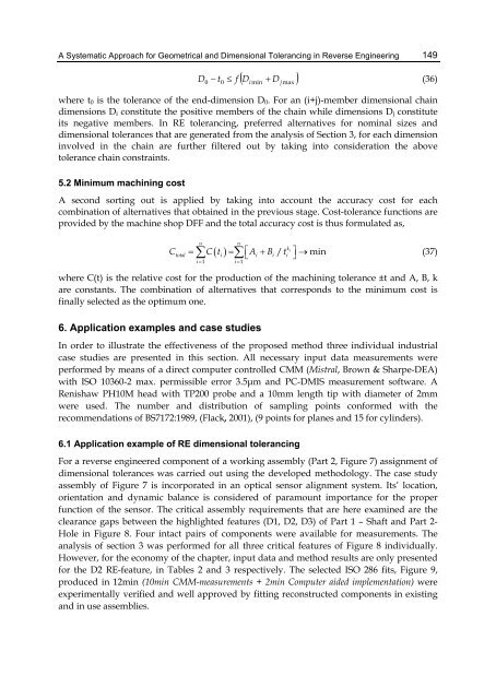
where t0 is the tolerance of the end-dimension D0. For an (i+j)-member dimensional chain<br />
dimensions Di constitute the positive members of the chain while dimensions Dj constitute<br />
its negative members. In RE tolerancing, preferred alternatives for nominal sizes <strong>and</strong><br />
dimensional tolerances that are generated from the analysis of Section 3, for each dimension<br />
involved in the chain are further filtered out by taking into consideration the above<br />
tolerance chain constraints.<br />
5.2 Minimum machining cost<br />
A second sorting out is applied by taking into account the accuracy cost for each<br />
combination of alternatives that obtained in the previous stage. Cost-tolerance functions are<br />
provided by the machine shop DFF <strong>and</strong> the total accuracy cost is thus formulated as,<br />
total<br />
n<br />
� � i �<br />
n<br />
� i i<br />
ki<br />
i<br />
i�1 i�1<br />
C � C t � �<br />
�A �B / t �<br />
��min<br />
where C(t) is the relative cost for the production of the machining tolerance ±t <strong>and</strong> A, B, k<br />
are constants. The combination of alternatives that corresponds to the minimum cost is<br />
finally selected as the optimum one.<br />
6. Application examples <strong>and</strong> case studies<br />
In order to illustrate the effectiveness of the proposed method three individual industrial<br />
case studies are presented in this section. All necessary input data measurements were<br />
performed by means of a direct computer controlled CMM (Mistral, Brown & Sharpe-DEA)<br />
with ISO 10360-2 max. permissible error 3.5μm <strong>and</strong> PC-DMIS measurement software. A<br />
Renishaw PH10M head with TP200 probe <strong>and</strong> a 10mm length tip with diameter of 2mm<br />
were used. The number <strong>and</strong> distribution of sampling points conformed with the<br />
recommendations of BS7172:1989, (Flack, 2001), (9 points for planes <strong>and</strong> 15 for cylinders).<br />
6.1 Application example of RE dimensional tolerancing<br />
For a <strong>reverse</strong> engineered component of a working assembly (Part 2, Figure 7) assignment of<br />
dimensional tolerances was carried out using the developed methodology. The case study<br />
assembly of Figure 7 is incorporated in an optical sensor alignment system. Its’ location,<br />
orientation <strong>and</strong> dynamic balance is considered of paramount importance for the proper<br />
function of the sensor. The critical assembly requirements that are here examined are the<br />
clearance gaps between the highlighted features (D1, D2, D3) of Part 1 <strong>–</strong> Shaft <strong>and</strong> Part 2-<br />
Hole in Figure 8. Four intact pairs of components were available for measurements. The<br />
analysis of section 3 was performed for all three critical features of Figure 8 individually.<br />
However, for the economy of the chapter, input data <strong>and</strong> method results are only presented<br />
for the D2 RE-feature, in Tables 2 <strong>and</strong> 3 respectively. The selected ISO 286 fits, Figure 9,<br />
produced in 12min (10min CMM-measurements + 2min Computer aided implementation) were<br />
experimentally verified <strong>and</strong> well approved by fitting reconstructed components in existing<br />
<strong>and</strong> in use assemblies.<br />
149<br />
(36)<br />
(37)