reverse engineering – recent advances and applications - OpenLibra
reverse engineering – recent advances and applications - OpenLibra
reverse engineering – recent advances and applications - OpenLibra

You also want an ePaper? Increase the reach of your titles
YUMPU automatically turns print PDFs into web optimized ePapers that Google loves.
180<br />
Reverse Engineering <strong>–</strong> Recent Advances <strong>and</strong> Applications<br />
Analyzer. The solid model generated is extremely accurate, where geometric error measured<br />
in average <strong>and</strong> st<strong>and</strong>ard deviation is 0.0002 <strong>and</strong> 0.0017 in., respectively (between the solid<br />
model <strong>and</strong> point cloud). Since the model is fully parameterized, it can be modified by<br />
simply changing the dimension values. For example, the length of the base block can be<br />
increased for an extended model, as shown in Fig. 18c.<br />
Method 2: Wizard<br />
Wizard, or Modeling Wizard, of Rapidform automatically extracts Wizard features such as<br />
extrude, revolve, pipe, <strong>and</strong> loft, etc., to create solid models from segmented regions. Note<br />
that a Wizard feature can be a surface (such as pipe) or a solid feature. There are five Wizard<br />
features provided: extrusion, revolution for extracting solid features; <strong>and</strong> sweep, loft, <strong>and</strong> pipe<br />
for surface features. There are three general steps to extract features using Wizard, (1) select<br />
mesh segments to generate individual features using Wizard, (2) modify the dimensions or<br />
add constraints to the sketches extracted in order to parameterize the sketches, <strong>and</strong> (3) use<br />
Boolean operations to union, subtract, or intersect individual features for a final model if<br />
needed.<br />
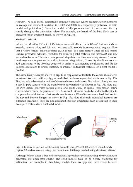
The same tubing example shown in Fig. 19 is employed to illustrate the capabilities offered<br />
in Wizard. We start with a polygon mesh that has been segmented, as shown in Fig. 19a.<br />
First, we select the exterior region of the main branch <strong>and</strong> choose Pipe Wizard. Rapidform uses<br />
a best fit pipe surface to fit the main branch automatically, as shown in Fig. 19b. Note that<br />
the Pipe Wizard generates section profile <strong>and</strong> guide curve as spatial (non-planar) spline<br />
curves, which cannot be parameterized. Also, wall thickness has to be added to the pipe to<br />
complete the solid feature. Next, we choose Revolution Wizard to create revolved features for<br />
the top <strong>and</strong> bottom flanges, as shown in Fig. 19c. Note that each individual features are<br />
extracted separately. They are not associated. Boolean operations must be applied to these<br />
decoupled features for a final solid model.<br />
Fig. 19. Feature extraction for the tubing example using Wizard, (a) selected main branch<br />
region, (b) surface created using Pipe Wizard, <strong>and</strong> (c) flange created using Revolution Wizard<br />
Although Wizard offers a fast <strong>and</strong> convenient approach for solid modeling, the solid models<br />
generated are often problematic. The solid models have to be closely examined for<br />
validation. For example, in this tubing model, there are gap <strong>and</strong> interference between