reverse engineering – recent advances and applications - OpenLibra
reverse engineering – recent advances and applications - OpenLibra
reverse engineering – recent advances and applications - OpenLibra

You also want an ePaper? Increase the reach of your titles
YUMPU automatically turns print PDFs into web optimized ePapers that Google loves.
178<br />
Reverse Engineering <strong>–</strong> Recent Advances <strong>and</strong> Applications<br />
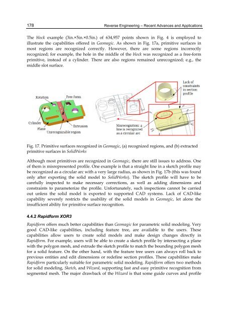
The block example (3in.×5in.×0.5in.) of 634,957 points shown in Fig. 4 is employed to<br />
illustrate the capabilities offered in Geomagic. As shown in Fig. 17a, primitive surfaces in<br />
most regions are recognized correctly. However, there are some regions incorrectly<br />
recognized; for example, the hole in the middle of the block was recognized as a free-form<br />
primitive, instead of a cylinder. There are also regions remained unrecognized; e.g., the<br />
middle slot surface.<br />
Fig. 17. Primitive surfaces recognized in Geomagic, (a) recognized regions, <strong>and</strong> (b) extracted<br />
primitive surfaces in SolidWorks<br />
Although most primitives are recognized in Geomagic, there are still issues to address. One<br />
of them is misrepresented profile. One example is that a straight line in a sketch profile may<br />
be recognized as a circular arc with a very large radius, as shown in Fig. 17b (this was found<br />
only after exporting the solid model to SolidWorks). The sketch profile will have to be<br />
carefully inspected to make necessary corrections, as well as adding dimensions <strong>and</strong><br />
constraints to parameterize the profile. Unfortunately, such inspections cannot be carried<br />
out unless the solid model is exported to supported CAD systems. Lack of CAD-like<br />
capability severely restricts the usability of the solid models in Geomagic, let alone the<br />
insufficient ability for primitive surface recognition.<br />
4.4.2 Rapidform XOR3<br />
Rapidform offers much better capabilities than Geomagic for parametric solid modeling. Very<br />
good CAD-like capabilities, including feature tree, are available to the users. These<br />
capabilities allow users to create solid models <strong>and</strong> make design changes directly in<br />
Rapidform. For example, users will be able to create a sketch profile by intersecting a plane<br />
with the polygon mesh, <strong>and</strong> extrude the sketch profile to match the bounding polygon mesh<br />
for a solid feature. On the other h<strong>and</strong>, with the feature tree users can always roll back to<br />
previous entities <strong>and</strong> edit dimensions or redefine section profiles. These capabilities make<br />
Rapidform particularly suitable for parametric solid modeling. Rapidform offers two methods<br />
for solid modeling, Sketch, <strong>and</strong> Wizard, supporting fast <strong>and</strong> easy primitive recognition from<br />
segmented mesh. The major drawback of the Wizard is that some guide curves <strong>and</strong> profile