reverse engineering – recent advances and applications - OpenLibra
reverse engineering – recent advances and applications - OpenLibra
reverse engineering – recent advances and applications - OpenLibra

You also want an ePaper? Increase the reach of your titles
YUMPU automatically turns print PDFs into web optimized ePapers that Google loves.
A Review on Shape Engineering <strong>and</strong> Design Parameterization in Reverse Engineering<br />
CATIA, capable of recognizing basic features, such as extrude, revolve, <strong>and</strong> more <strong>recent</strong>ly,<br />
sweep. This capability has been applied primarily for support of solid model interchanges<br />
between CAD packages with some success, in which not only geometric entities (as has been<br />
done by IGES�Initial Graphics Exchange St<strong>and</strong>ards) but also parametric features are<br />
translated.<br />
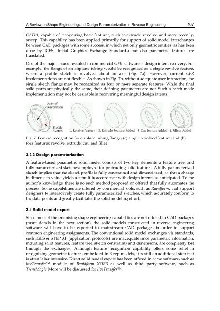
One of the major issues revealed in commercial GFR software is design intent recovery. For<br />
example, the flange of an airplane tubing would be recognized as a single revolve feature,<br />
where a profile sketch is revolved about an axis (Fig. 7a). However, current GFR<br />
implementations are not flexible. As shown in Fig. 7b, without adequate user interaction, the<br />
single sketch flange may be recognized as four or more separate features. While the final<br />
solid parts are physically the same, their defining parameters are not. Such a batch mode<br />
implementation may not be desirable in recovering meaningful design intents.<br />
Fig. 7. Feature recognition for airplane tubing flange, (a) single revolved feature, <strong>and</strong> (b)<br />
four features: revolve, extrude, cut, <strong>and</strong> fillet<br />
3.3.3 Design parameterization<br />
A feature-based parametric solid model consists of two key elements: a feature tree, <strong>and</strong><br />
fully parameterized sketches employed for protruding solid features. A fully parameterized<br />
sketch implies that the sketch profile is fully constrained <strong>and</strong> dimensioned, so that a change<br />
in dimension value yields a rebuilt in accordance with design intents as anticipated. To the<br />
author’s knowledge, there is no such method proposed or offered that fully automates the<br />
process. Some capabilities are offered by commercial tools, such as Rapidform, that support<br />
designers to interactively create fully parameterized sketches, which accurately conform to<br />
the data points <strong>and</strong> greatly facilitates the solid modeling effort.<br />
3.4 Solid model export<br />
Since most of the promising shape <strong>engineering</strong> capabilities are not offered in CAD packages<br />
(more details in the next section), the solid models constructed in <strong>reverse</strong> <strong>engineering</strong><br />
software will have to be exported to mainstream CAD packages in order to support<br />
common <strong>engineering</strong> assignments. The conventional solid model exchanges via st<strong>and</strong>ards,<br />
such IGES or STEP AP (application protocols), are inadequate since parametric information,<br />
including solid features, feature tree, sketch constraints <strong>and</strong> dimensions, are completely lost<br />
through the exchanges. Although feature recognition capability offers some relief in<br />
recognizing geometric features embedded in B-rep models, it is still an additional step that<br />
is often labor intensive. Direct solid model export has been offered in some software, such as<br />
liveTransfer module of Rapidform XOR3 as well as third party software, such as<br />
TransMagic. More will be discussed for liveTransfer.<br />
167