reverse engineering – recent advances and applications - OpenLibra
reverse engineering – recent advances and applications - OpenLibra
reverse engineering – recent advances and applications - OpenLibra

You also want an ePaper? Increase the reach of your titles
YUMPU automatically turns print PDFs into web optimized ePapers that Google loves.
174<br />
Reverse Engineering <strong>–</strong> Recent Advances <strong>and</strong> Applications<br />
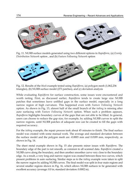
Fig. 11. NURB surface models generated using two different options in Rapidform, (a) Evenly<br />
Distribution Network option , <strong>and</strong> (b) Feature Following Network option<br />
Fig. 12. Results of the block example tested using Rapidform, (a) polygon mesh (1,062,236<br />
triangles), (b) NURB surface model (273 patches), <strong>and</strong> (c) deviation analysis<br />
While evaluating Rapidform for surface construction, some issues were encountered <strong>and</strong><br />
worth noting. First, as discussed earlier, Rapidform tends to create large size NURB<br />
patches that sometimes leave unfilled gaps in the surface model, especially in a long<br />
narrow region of high curvature. This happened even with Feature Following Network<br />
option. As shown in Fig. 13, almost half of the small branch of the tubing is missing after<br />
auto surfacing with Feature Following Network option. When such a problem appears,<br />
Rapidform highlights boundary curves of the gaps that are not able to be filled. In general,<br />
users can choose to reduce the gap size, for example, by adding NURB curves to split the<br />
narrow regions, until NURB patches of adequate size can be created to fill the gaps with<br />
required accuracy.<br />
For the tubing example, the repair process took about 45 minutes to finish. The final surface<br />
model was created with some manual work. The average <strong>and</strong> st<strong>and</strong>ard deviation between<br />
the surface model <strong>and</strong> the polygon mesh are -0.0003 mm <strong>and</strong> 0.0189 mm, respectively, as<br />
shown in Fig. 14.<br />
The sheet metal example shown in Fig. 15 also presents minor issues with Rapidform. The<br />
boundary edge of the part is not smooth, as common to all scanned data. Rapidform created a<br />
NURB curve along the boundary, <strong>and</strong> then another smoother curve very close to the boundary<br />
edge. As a result, a very long <strong>and</strong> narrow region was created between these two curves, which<br />
present problems in auto surfacing. Similar steps as to the tubing example were taken to split<br />
the narrow region by adding NURB curves. The final model was split in four main regions <strong>and</strong><br />
several smaller regions shown in Fig. 16, which allows NURB surfaces to be generated with<br />
excellent accuracy (average: 0.0 in, st<strong>and</strong>ard deviation: 0.0002 in).