DM_RAP_COMBI_rev03 IN LAVORO.pmd - Opico
DM_RAP_COMBI_rev03 IN LAVORO.pmd - Opico
DM_RAP_COMBI_rev03 IN LAVORO.pmd - Opico

You also want an ePaper? Increase the reach of your titles
YUMPU automatically turns print PDFs into web optimized ePapers that Google loves.
ITALIANO<br />
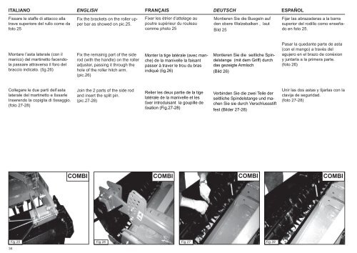
Fissare le staffe di attacco alla<br />
trave superiore del rullo come da<br />
foto 25<br />
ENGLISH FRANÇAIS DEUTSCH<br />
ESPAÑOL<br />
Fix the brackets on the roller upper<br />
bar as showed on pic.25.<br />
Fixer les étrier d’attelage au<br />
poutre supérieur du rouleau<br />
comme photo 25<br />
Montieren Sie die Buegeln auf<br />
den obere Walzebalken , laut<br />
Bild 25<br />
Fijar las abrazaderas a la barra<br />
superior del rodillo como enseñado<br />
en foto 25.<br />
Montare l’asta laterale (con il<br />
manico) del martinetto facendola<br />
passare attraverso il foro del<br />
braccio indicato. (fi g.26)<br />
Fix the remainig part of the side<br />
rod (with the handle) on the roller<br />
adjuster, passing it through the<br />
hole of the roller hitch arm.<br />
(pic.26)<br />
Monter la tige latérale (avec manche)<br />
de la manivelle la faisant<br />
passer à traver le trou du bras<br />
indiqué (fi g.26)<br />
Montieren Sie die seitliche Spindelstange<br />
(mit dem Griff) durch<br />
das gezeigte Armloch<br />
(Bild 26)<br />
Pasar la quedante parte de asta<br />
(con el mango) a través del<br />
agujero en el brazo de conéxion<br />
y juntarla a la primera parte.<br />
(foto 26)<br />
Collegare le due parti dell’asta<br />
laterale del martinetto e fi ssarle<br />
Inserendo la copiglia di fi ssaggio.<br />
(foto 27-28)<br />
Join the 2 parts of the side rod<br />
and insert the split pin.<br />
(pic.27-28)<br />
Relier les deux partie de la tige<br />
latérale de la manivelle et les<br />
fi xer introduisant la goupille de<br />
fi xation (Fig.27-28)<br />
Verbinden Sie die zwei Teile der<br />
seitlliche Spindelstange und machen<br />
Sie sie durch Verschlussstift<br />
fest (Bilder 27-28)<br />
Unir las dos astas y fi jarlas con la<br />
clavija de seguridad.<br />
(foto 27-28)<br />
<strong>COMBI</strong> <strong>COMBI</strong> <strong>COMBI</strong> <strong>COMBI</strong><br />
Fig.25<br />
34<br />
Fig.26 Fig.27 Fig.28