DM_RAP_COMBI_rev03 IN LAVORO.pmd - Opico
DM_RAP_COMBI_rev03 IN LAVORO.pmd - Opico
DM_RAP_COMBI_rev03 IN LAVORO.pmd - Opico

Create successful ePaper yourself
Turn your PDF publications into a flip-book with our unique Google optimized e-Paper software.
ITALIANO<br />
3.9 PROFONDITÀ DI<br />
<strong>LAVORO</strong><br />
La regolazione della profondità di lavoro<br />
della macchina viene determinata dalla<br />
posizione del rullo livellatore.<br />
3.10 REGOLAZIONE RULLI<br />
La regolazione dei rulli può essere:<br />
Idraulica<br />
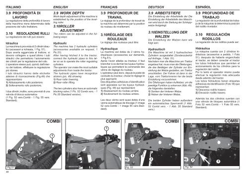
La macchina è provvista di 2 cilindri idraulici<br />
(accessori a richiesta, 1 Fig. 51).<br />
Dopo averla agganciata al trattore, si<br />
devono collegare a quest’ultimo i tubi<br />
idraulici che permettono l’azionamento<br />
dei cilindri per la regolazione del rullo.<br />
L’operatore stesso può, quindi, dall’interno<br />
del trattore, effettuare la regolazione<br />
più idonea.<br />
I tubi idraulici hanno delle etichette<br />
adesive di riconoscimento (Fig.49) che<br />
rappresentano<br />
1) Abbassamento rullo posteriore.<br />
2) Sollevamento rullo posteriore.<br />
I due cilindri, inoltre, sono provvisti di una<br />
valvola di blocco automatica<br />
(1 Fig. 52 vers.Combi - 1 Fig. 55 vers.<br />
Standard).<br />
ENGLISH FRANÇAIS DEUTSCH<br />
ESPAÑOL<br />
3.9 WORK DEPTH<br />
Work depth adjustment of the machine is<br />
established by the position of the levelling<br />
roller.<br />
3.10 ROLLER<br />
ADJUSTMENT<br />
The rollers can be adjusted in the following<br />
ways:<br />
Hydraulic<br />
The machine has 2 hydraulic cylinders<br />
(accessories available on request, 1<br />
Pic.51).<br />
After having hitched it to the tractor,<br />
connect the hydraulic pipes to this latter<br />
so as to operate the roller regulating<br />
cylinders.<br />
The operator can make the most suitable<br />
adjustments from inside the tractor.<br />
The hydraulic pipes have recognition<br />
stickers (pic. 49) showing<br />
1) Rear roller lowering.<br />
2) Rear roller lifting.<br />
The two cylinders also have an automatic<br />
blocking valve (1 Pic. 52 Combi vers. - 1<br />
Pic.55 Standard version).<br />
3.9 PROFONDEUR DE<br />
TRAVAIL<br />
Le réglage de la profondeur de travail de<br />
la machine est déterminé par la position<br />
du rouleau de nivellement.<br />
3.10 RÉGLAGE DES<br />
ROULEAUX<br />
Le réglage des rouleaux peut être:<br />
Hydraulique<br />
La machine est dotée de 2 vérins hydrauliques<br />
(accessoires sur demande,<br />
1 Fig.51).<br />
Après l’avoir attelée au tracteur, il faut<br />
brancher à ce dernier les tuyaux hydrauliques<br />
qui permettent la commande des<br />
vérins de réglage du rouleau.<br />
L’opérateur peut donc, depuis le poste de<br />
conduite du tracteur, choisir le réglage le<br />
plus approprié.<br />
Des étiquettes adhésives d’identifi cation<br />
sont apposées sur les tuyaux hydrauliques<br />
(Fig. 49) qui représentent<br />
1) Abaissement du rouleau arrière.<br />
2) Soulèvement du rouleau arrière.<br />
Les deux vérins sont aussi dotés d’une<br />
vanne automatique de blocage (1 image<br />
52 vers.Combi - 1 image 55 vers.Standard).<br />
3.9 ARBEITSTIEFE<br />
Die Einstellung der Arbeitstiefe der Die<br />
Einstellung der Arbeitstiefe des Maschinen<br />
wird durch die Stellung der Schleppwalze<br />
festgelegt.<br />
3.10 E<strong>IN</strong>STELLUNG DER<br />
WALZEN<br />
Die Einstellung der Walzen kann wie<br />
folgt sein:<br />
Hydraulisch<br />
Die Maschine ist mit 2 hydraulischen<br />
Zylindern ausgestattet (Sonderzubehör<br />
auf Anfrage, 1 Abb. 51).<br />
Nachdem man die Maschine am Traktor<br />
angebaut hat, muss man die Ölleitungen,<br />
die das Betätigen der Zylinder zur Einstellung<br />
der Walze gestatten, am Traktor<br />
anschließen. Der Fahrer ist dann in der<br />
Lage, vom Traktorinneren her die beste<br />
Einstellung vorzunehmen.<br />
Die Ölleitungen haben Aufkleber, um die<br />
jeweilige Funktion zu erkennen (Abb. 49),<br />
die folgendes darstellen:<br />
1) Senken der hinteren Walze.<br />
2) Heben der hinteren Walze.<br />
Die beiden Zylinder haben außerdem<br />
ein automatisches Sperrventil (1 Abb.<br />
52 Combi vers. - 1 Abb. 55 Standard<br />
vers.).<br />
3.9 PROFUNDIDAD DE<br />
TRABAJO<br />
La regulación de la profundidad de trabajo<br />
de la máquinas la determina la posición<br />
del rodillo nivelador.<br />
3.10 REGULACIÓN<br />
RODILLOS<br />
La regulación de los rodillos puede ser:<br />
Hidráulica<br />
La máquina cuenta con 2 cilindros hidráulicos<br />
(accesorios a pedido, 1 Foto<br />
51); después de haberla enganchado<br />
al tractor, se deben conectar al tractor<br />
los tubos hidráulicos que permiten el<br />
accionamiento de los cilindros para la<br />
regulación del rodillo.<br />
Por lo tanto el operador mismo puede<br />
efectuar la regulación más adecuada<br />
desde adentro del tractor.<br />
Los tubos hidráulicos tienen etiquetas<br />
adhesivas de identificación (Foto 18) que<br />
representan:<br />
1) Descenso rodillo trasero.<br />
2) Elevación rodillo trasero.<br />
Además los dos cilindros cuentan con<br />
una válvula de bloqueo automática (1<br />
Foto 52 vers.Combi - 1 Foto 55 vers.<br />
Standard).<br />
<strong>COMBI</strong> <strong>COMBI</strong> <strong>COMBI</strong> <strong>COMBI</strong><br />
1<br />
1<br />
1<br />
1<br />
1<br />
2<br />
3<br />
2<br />
3<br />
48<br />
Fig.51<br />
Fig. 52<br />
Fig. 53 Fig. 54