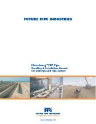
Installation Manual - Future Pipe Industries
Installation Manual - Future Pipe Industries
Installation Manual - Future Pipe Industries

You also want an ePaper? Increase the reach of your titles
YUMPU automatically turns print PDFs into web optimized ePapers that Google loves.
11. Field test procedure<br />
Before the installed pipe system can be used, the system needs to be tested to ensure that all the joints function<br />
correctly. The test equipment must be suited to the diameter and pressure, and be able to reach the required test<br />
pressure. If the pipe system ends with a flange, a steel blind flange, which has connections for filling and air release,<br />
can easily be connected. The pressure gauge must be connected between the valve and the system in order to indicate<br />
the pressure after the valve is closed. Due to the head of water, the pressure gauge should be located at the lowest<br />
point. The pressure gauge should have a full scale reading of about twice the test pressure.<br />
If the system has not been designed to withstand any negative pressures and this occurs during testing, the system<br />
needs to be protected by an air release valve. Trapped air can be released using a vent at the highest point in<br />
the system.<br />
11.1. Filling, stabilizing and testing<br />
Fill with water at the lowest point in the line using a small diameter branch connection and vent the trapped<br />
air at the highest point(s). Long straight sections may be vented using an inflatable ball or foam pig to expel any<br />
air and impurities.<br />
Fig. 11.1.a.<br />
After filling, the line must be pressurized gradually at 0.8 times working pressure dependent on the system and must<br />
be maintained for 24 hours allowing the pipe system to set. After the system is stabilized, the pressure must be raised<br />
gradually to 1.5 times working pressure and maintained for 4 hours.<br />
After 4 hours the pressure may have dropped by 0.5 bar for diam. ( 500 mm and 0.3 bar for diam. ( 450 mm per<br />
1000 metre length. The test pressure and its tolerance should be determined in advance.<br />
It is preferable to test the line in sections, for example the length of one day installation, which will be shut off by<br />
a temporary flanged joint and a ball. The blind flange should be provided with an air release valve. After testing<br />
the section, the ball needs to be pushed back about 2 metres using air via the air release valve. The excess water<br />
needs to be released by opening the valve at the start of the line. After the ball has been secured by inflating it,<br />
the temporary flange connection can be removed and assembly can continue.<br />
The advantage of this method is that the line does not need to be re-filled every time.<br />
During the test of underground systems, the trench must be partially backfilled and compacted, but the joints should<br />
be left exposed. Temporary anchors at directional changes should be applied.<br />
Any leak which occurs caused by wrong assembly of the joints can be easily detected. Extreme movements can<br />
be prevented by partly filling and compacting the trench.<br />
Wavistrong <strong>Installation</strong> <strong>Manual</strong><br />
59