- Page 1 and 2:
GAIL (INDIA) LTD NEW DELHI GAIL (In
- Page 3 and 4:
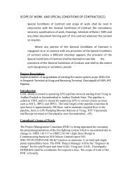
ANNEXURE - I CONTRACTOR’S SCOPE O
- Page 5 and 6:
1.3 Any activity specifically not l
- Page 7 and 8:
converter, barriers, relays, cables
- Page 9 and 10:
standards etc. and obtaining all re
- Page 11 and 12:
c) Contractor shall prepare purchas
- Page 13 and 14:
) The gas custody transfer metering
- Page 15 and 16:
q) Platforms & cross over to be pro
- Page 17 and 18:
nn) Dual Isolation Valves shall be
- Page 19 and 20:
3.2.1 Design and terminology shall
- Page 21 and 22:
GAIL (INDIA) LTD NEW DELHI IEC-6033
- Page 23 and 24:
Necessary filtration and double sta
- Page 25 and 26:
3.3.3.4 All instruments in the unit
- Page 27 and 28:
3.4.2.6 Junction boxes (as per the
- Page 29 and 30:
Typical gas composition S.N PARAMET
- Page 31 and 32:
� Pressure Class of Skid up to PR
- Page 33 and 34:
esponsibility for delivering equipm
- Page 35 and 36:
principal grain flow and notched pe
- Page 37 and 38:
carried out at manufacturer’s wor
- Page 39 and 40:
(e) Bubble wrapping as well as tran
- Page 41 and 42:
Mandatory Spares: Shall be provided
- Page 43 and 44:
application. Type approval certific
- Page 45 and 46:
16 Temperature gauges and Thermowel
- Page 47 and 48:
24 Standard specification for Inspe
- Page 49 and 50:
GAIL (INDIA) LTD NEW DELHI JOB SPEC
- Page 51 and 52:
1.0 Introduction 1.1 General 1.2 Sc
- Page 53 and 54:
ISO 170125: Calibration of all prim
- Page 55 and 56:
separate limit switches for open an
- Page 57 and 58:
measurement will not degrade by mor
- Page 59 and 60:
computer for custody transfer flow
- Page 61 and 62:
l) A statement of uncertainty for t
- Page 63 and 64: The flow computers shall be Micropr
- Page 65 and 66: KEYBOARD CAPABILITY: The data entry
- Page 67 and 68: Energy - Mcal/MMBTU/ MJ (user selec
- Page 69 and 70: LEL detectors/transmitters shall be
- Page 71 and 72: � The control panel shall also ha
- Page 73 and 74: GAIL (INDIA) LTD NEW DELHI ii) Anal
- Page 75 and 76: Metering supervisory system shall b
- Page 77 and 78: egulating the sample pressure & flo
- Page 79 and 80: III. Mole % CO2 IV. Mole % N2 Each
- Page 81 and 82: and ±0.5 % for components (mole%)
- Page 83 and 84: 9 Accessories Cell Battery and Char
- Page 85 and 86: S NO. TITLE 1 GENERAL CONTENTS 2 DE
- Page 87 and 88: 2.5 Standards 2.5.1 The instrumenta
- Page 89 and 90: 3.2.23 Supply of all types of consu
- Page 91 and 92: 4.3.1 Multitube/Multicore cables sh
- Page 93 and 94: 4.8.4 Cables shall have complete un
- Page 95 and 96: 4.12.1 All instruments shall be cal
- Page 97 and 98: ) Current generator (Instrument che
- Page 99 and 100: 7.0 MATERIALS SUPPLY 7.1 Materials
- Page 101 and 102: STANDARD SPECIFICATION FOR INSTRUME
- Page 103 and 104: 1 0 GENERAL 1.1 Scope 1.1.1 This st
- Page 105 and 106: per ASTM B 68M copper No. C 12200.
- Page 107 and 108: MAXIMUM WORKING PRESSURE AND HYDROS
- Page 109 and 110: NO. TITLE 1.0 GENERAL 2.0 DESIGN PH
- Page 111 and 112: d) List of deviations, if any, from
- Page 113: IS-3624 Specification for pressure
- Page 117 and 118: 2 DESIGN PHILOSOPHY 2.1 Instrumenta
- Page 119 and 120: approval from purchaser. c) In case
- Page 121 and 122: 2.14.1.6 Automatic sequential start
- Page 123 and 124: 2.21.1 Instrument junction boxes sh
- Page 125 and 126: side. 2.24 Philosophy of Junction B
- Page 127 and 128: ) All relays and solenoid valves sh
- Page 129 and 130: d) All receiver instruments shall b
- Page 131 and 132: lamp test push button shall be used
- Page 133 and 134: 4.4.6 All hinges, screws and other
- Page 135 and 136: The type of thermocouple shall be s
- Page 137 and 138: operating value. c) Pressure switch
- Page 139 and 140: level gauges shall have side mounte
- Page 141 and 142: The integral flow assembly shall be
- Page 143 and 144: of valve like butterfly, ball, rota
- Page 145 and 146: drawings alongwith the timing calcu
- Page 147 and 148: 4.13.9 All accessories like positio
- Page 149 and 150: 4.16.1 Vibration and axial displace
- Page 151 and 152: of 140 to 150 kg/cm2g while chargin
- Page 153 and 154: eceiver at the camera side. The con
- Page 155 and 156: 7.3 If at any point of time during
- Page 157 and 158: - rotary equipment running data etc
- Page 159 and 160: individual alarm in DCS. 7.12.5 All
- Page 161 and 162: 7.14.25 Wiring colour code within t
- Page 163 and 164: shall be routed to process or flare
- Page 165 and 166:
IP 55 and flame proof Ex˜d˜ suita
- Page 167 and 168:
Each components and the system shal
- Page 169 and 170:
f) All multi pair cables shall have
- Page 171 and 172:
) Monel or any other tubing shall b
- Page 173 and 174:
complete the job in all respect. 13
- Page 175 and 176:
provided. v) For impulse line with
- Page 177 and 178:
cables for insulation testing, ensu
- Page 179 and 180:
calibrate the instruments which sha
- Page 181 and 182:
LTD STANDARD SPECIFICATION FOR GAS
- Page 183 and 184:
LTD 1.1.1 This specification, toget
- Page 185 and 186:
LTD 2.2 Gas detection system shall
- Page 187 and 188:
LTD 2.10.8 Software features a) Dat
- Page 189 and 190:
LTD paint, colour as specified in J
- Page 191 and 192:
LTD 2.13.3.1 Alarm annunciator shal
- Page 193 and 194:
STANDARD SPECIFICATION FOR PRESSURE
- Page 195 and 196:
1.0 GENERAL 1.1 Scope 1.1.1 This sp
- Page 197 and 198:
a) Specification sheet for each gau
- Page 199 and 200:
d) Flange face shall be as per clau
- Page 201 and 202:
6.0 REJECTION 6.1 Vendor shall prep
- Page 203 and 204:
STANDARD SPECIFICATION FOR SELF ACT
- Page 205 and 206:
1.0 GENERAL 1.1 Scope 1.1.1 This st
- Page 207 and 208:
summing up all the deviations, from
- Page 209 and 210:
egulators shall have flanged end co
- Page 211 and 212:
2.6 Finish 2.6.1 The body shall be
- Page 213 and 214:
6.0 REJECTION 6.1 Vendor shall prep
- Page 215 and 216:
LTD S NO. TITLE 1 GENERAL CONTENTS
- Page 217 and 218:
LTD 1.1.3 In the event of any confl
- Page 219 and 220:
LTD d) Ring type joint flanges shal
- Page 221 and 222:
LTD 2.6.6 In general, an actuator o
- Page 223 and 224:
LTD Linearity and Hysterisis shall
- Page 225 and 226:
GAIL (INDIA) LTD NEW DELHI Abbrevia
- Page 227 and 228:
1.0 GENERAL 1.1 Scope 1.1.1 This sp
- Page 229 and 230:
) Minimum number of eight PVC / rub
- Page 231 and 232:
Smoke density rating not to exceed
- Page 233 and 234:
iii) Shrinkage test iv) Hot deforma
- Page 235 and 236:
GAIL (INDIA) LTD NEW DELHI STANDARD
- Page 237 and 238:
CONTENTS 1.0 GENERAL 2.0 DESIGN AND
- Page 239 and 240:
1.1.3 In the event of any conflict
- Page 241 and 242:
the terminal block for terminating
- Page 243 and 244:
3.2.1 The following information sha
- Page 245 and 246:
GAIL (INDIA) LTD NEW DELHI STANDARD
- Page 247 and 248:
CONTENTS 1.0 GENERAL 2.0 DESIGNS AN
- Page 249 and 250:
specifically indicated, the specifi
- Page 251 and 252:
sheet, the number of terminals for
- Page 253 and 254:
4.3.2 In the event when witness ins
- Page 255 and 256:
1 GENERAL CONTENTS 2 DESIGN AND CON
- Page 257 and 258:
attached along with the material re
- Page 259 and 260:
4.2 review: fittings. Vendor shall
- Page 261 and 262:
GAIL (INDIA) LTD NEW DELHI HYDROSTA
- Page 263 and 264:
1.0 GENERAL 2.0 DESIGN AND CONSTRUC
- Page 265 and 266:
IS-2148 Electrical Apparatus for Ex
- Page 267 and 268:
1.3 Drawing and Data 1.3.1 Detailed
- Page 269 and 270:
1 Instruments Bottom Row Middle Row
- Page 271 and 272:
a) 50 mm minimum space shall be pro
- Page 273 and 274:
4.1 Unless otherwise specified, pur
- Page 275 and 276:
GAIL (INDIA) LTD NEW DELHI STANDARD
- Page 277 and 278:
1.0 GENERAL 2.0 DESIGN AND CONSTRUC
- Page 279 and 280:
detailed technical offer is require
- Page 281 and 282:
double block and bleed for the bypa
- Page 283 and 284:
Annexure-1 of this specification. D
- Page 285 and 286:
GAIL (INDIA) LTD NEW DELHI STANDARD
- Page 287 and 288:
1.1 Scope 1.1.1 This specification,
- Page 289 and 290:
proto-type design or items not meet
- Page 291 and 292:
2.3.1 Body 2.3.1.1 Unless otherwise
- Page 293 and 294:
connections shall be blinded / plug
- Page 295 and 296:
) Hydrostatic test as per clause 4.
- Page 297 and 298:
GAIL (INDIA) LTD NEW DELHI Abbrevia
- Page 299 and 300:
1.0 General 1.1 Scope 1.1.2 This sp
- Page 301 and 302:
manufactured outside India. e) Devi
- Page 303 and 304:
Weatherproof housing IP-65 to IEC-6
- Page 305 and 306:
alarm is provided as diagnostic mai
- Page 307 and 308:
extra functionality and/or software
- Page 309 and 310:
) Reading coefficient, if any c) Pe
- Page 311 and 312:
6.0 REJECTION 6.1 Vendor shall prep
- Page 313 and 314:
Annexure 2 GASKETS MATERIAL REQUIRE
- Page 315 and 316:
1.0 GENERAL GAIL (INDIA) LTD NEW DE
- Page 317 and 318:
esponsibility shall include the fol
- Page 319 and 320:
2.1.1 Temperature gauges shall be o
- Page 321 and 322:
) Flanged end connections shall be
- Page 323 and 324:
f) Review of all certificates and t
- Page 325 and 326:
LTD SECTION 1.0 GENERAL TABLE of CO
- Page 327 and 328:
LTD without any commercial implicat
- Page 329 and 330:
LTD IEC 60079 Electrical Apparatus
- Page 331 and 332:
LTD Direction of flow 4.9 Field act
- Page 333 and 334:
LTD meters for the given process co
- Page 335 and 336:
LTD Uncorrected and corrected forwa
- Page 337 and 338:
LTD 9.1.1 PURCHASER may visit the p
- Page 339 and 340:
LTD 9.4.1 Site Acceptance shall con
- Page 341 and 342:
STANDARD SPECIFICATION FOR GAS CHRO
- Page 343 and 344:
1.0 SCOPE 9.1 This specification co
- Page 345 and 346:
H2S < ppm by weight S < ppm by weig
- Page 347 and 348:
5.2 After placement of purchase ord
- Page 349 and 350:
Gas Gr. IIA & IIB Temp T3. All anal
- Page 351 and 352:
classification indicated in the pur
- Page 353 and 354:
6.4.13 The programmer will be certi
- Page 355 and 356:
c) Temperature, pressure and flow r
- Page 357 and 358:
10.2 The approved spare parts and c
- Page 359 and 360:
CONTENTS 1.0 SCOPE 2.0 DEFINITIONS
- Page 361 and 362:
AGA Report No 3 Orifice Metering of
- Page 363 and 364:
5.2.2 Analog inputs shall be 4-20 m
- Page 365 and 366:
5.8.4 The minimum protocol supporte
- Page 367 and 368:
such a way that the flow controller
- Page 369 and 370:
6.3 GAS TURBINE METER CALCULATIONS
- Page 371 and 372:
7.0 DATA MANAGEMENT AND USER INTERF
- Page 373 and 374:
♦ Daily total of the standard vol
- Page 375 and 376:
♦ Hourly averages of differential
- Page 377 and 378:
♦ Calibrated Static Pressure Rang
- Page 379 and 380:
Analog input Analog output 8.3.3 A
- Page 381 and 382:
9.3.1 PURCHASER shall not be invite
- Page 383 and 384:
VENDOR shall provide a schedule det
- Page 385 and 386:
minimum the following topics shall
- Page 387 and 388:
GAIL (INDIA) LTD NEW DELHI THERMOCO
- Page 389 and 390:
GAIL (INDIA) LTD NEW DELHI THERMOWE
- Page 391 and 392:
GAIL (INDIA) LTD NEW DELHI THERMOWE
- Page 393 and 394:
GAIL (INDIA) LTD NEW DELHI INSTRUME
- Page 395 and 396:
GAIL (INDIA) LTD NEW DELHI INSTRUME
- Page 397 and 398:
GAIL (INDIA) LTD NEW DELHI SUPPORT
- Page 399 and 400:
GAIL (INDIA) LTD NEW DELHI CANOPY F
- Page 401 and 402:
GAIL (INDIA) LTD NEW DELHI TRAY SUP
- Page 403 and 404:
GAIL (INDIA) LTD NEW DELHI INSTRUME
- Page 405 and 406:
GAIL (INDIA) LTD NEW DELHI INSTRUME
- Page 407 and 408:
TUBING HOOK-UP WITH CONTROL VALVE A
- Page 409 and 410:
GAIL (INDIA) LTD NEW DELHI PRESSURE
- Page 411 and 412:
GAIL (INDIA) LTD NEW DELHI PRESSURE
- Page 413 and 414:
GAIL (INDIA) LTD NEW DELHI DP INSTR
- Page 415 and 416:
GAIL (INDIA) LTD NEW DELHI STANDARD
- Page 417 and 418:
GAIL (INDIA) LTD NEW DELHI STANDARD
- Page 419 and 420:
GAIL (INDIA) LTD NEW DELHI STANDARD
- Page 421 and 422:
GAIL (INDIA) LTD NEW DELHI DIMESION
- Page 423 and 424:
1.0 SCOPE 2.0 REFERENCE DOCUMENTS 3
- Page 425 and 426:
In case of conflict between the req
- Page 427 and 428:
GAIL (INDIA) LTD NEW DELHI movement
- Page 429 and 430:
4.25 All mounting accessories neede
- Page 431 and 432:
8.1 All threaded and flanged openin
- Page 433 and 434:
1. Stop Valve (3/4” NPT), 2. Chec
- Page 435 and 436:
SL. NO GAIL (INDIA) LTD NEW DELHI G
- Page 437 and 438:
1.0 SCOPE GAIL (INDIA) LTD NEW DELH
- Page 439 and 440:
ASTM A-370 - Standard Test Methods
- Page 441 and 442:
4.2 Valve body design shall be eith
- Page 443 and 444:
) Flanged end, if specified, shall
- Page 445 and 446:
d) Direction of operation of hand w
- Page 447 and 448:
5.1.7 a) All finished wrought weld
- Page 449 and 450:
) Test certificates of hydrostatic
- Page 451 and 452:
k) List of recommended spares requi
- Page 453 and 454:
STANDARD SPECIFICATION FOR PIPELINE
- Page 455 and 456:
1.0 SCOPE This Specification covers
- Page 457 and 458:
3.5 For all such valves where Carbo
- Page 459 and 460:
4.12 Valves shall be suitable for e
- Page 461 and 462:
) Body castings of valves shall be
- Page 463 and 464:
d) Test report on operation of valv
- Page 465 and 466:
c) Fabrication details of all valve
- Page 467 and 468:
GAIL (INDIA) LTD NEW DELHI STANDARD
- Page 469 and 470:
1.0 SCOPE This specification covers
- Page 471 and 472:
4.9 All welds shall be made by weld
- Page 473 and 474:
other suitable material. All valves
- Page 475 and 476:
STANDARD SPECIFICATION FOR SEAMLESS
- Page 477 and 478:
1.0 SCOPE This specification covers
- Page 479 and 480:
e used for other hydrocarbon servic
- Page 481 and 482:
9.0 DOCUMENTATION 9.1 Prior to ship
- Page 483 and 484:
1.0 SCOPE 2.0 REFERENCE DOCUMENTS 3
- Page 485 and 486:
MSS-SP-97 - Forged Carbon Steel Bra
- Page 487 and 488:
maintained. Repair welding procedur
- Page 489 and 490:
SPECIFICATION FOR QUICK OPENING END
- Page 491 and 492:
SCOPE This specification covers the
- Page 493 and 494:
4.6 End closure shall be provided w
- Page 495 and 496:
7.3 Before shipment, closures shall
- Page 497 and 498:
WELDING SPECIFICATION FOR FABRICATI
- Page 499 and 500:
(This specification shall be used i
- Page 501 and 502:
4.8 Tungsten electrodes used shall
- Page 503 and 504:
8.2 Cleaning (a) The ends to be wel
- Page 505 and 506:
GAIL (INDIA) LTD NEW DELHI Metal st
- Page 507 and 508:
(h) Manufacturer's test certificate
- Page 509 and 510:
Inspection of all welds shall be ca
- Page 511 and 512:
(a) Whenever such tests are specifi
- Page 513 and 514:
ELECTRODE QUALIFICATION TEST RECORD
- Page 515 and 516:
Macro Test Results : Fracture Test
- Page 517 and 518:
Soaking Time (Hrs.) _______________
- Page 519 and 520:
FILLER METALS GAIL (INDIA) LTD NEW
- Page 521 and 522:
GAIL (INDIA) LTD NEW DELHI EXHIBIT
- Page 523 and 524:
OTHER TESTS Type of Test __________
- Page 525 and 526:
Guided Bend Test Results Type of Fi
- Page 527 and 528:
1. Name: 2. Identification: 3. Date
- Page 529 and 530:
TECHNICAL NOTES FOR PIPES GAIL (IND
- Page 531 and 532:
GAIL (INDIA) LTD NEW DELHI Material
- Page 533 and 534:
Temp ( o F) Material A335 Gr. P 11
- Page 535 and 536:
3.0 HYDROSTATIC TEST 3.1 All pipes
- Page 537 and 538:
c) Stainless Steel E.FS.W (8” and
- Page 539 and 540:
S. NO. TITLE 1.0 GENERAL 2.0 DOCUME
- Page 541 and 542:
2.2.2 Test report shall be supplied
- Page 543 and 544:
GAIL (INDIA) LTD NEW DELHI ANSI 600
- Page 545 and 546:
3.18.5 The face-to-face dimensions
- Page 547 and 548:
4.3 Where gear operator is not call
- Page 549 and 550:
casting to be radiographed for type
- Page 551 and 552:
GAIL (INDIA) LTD NEW DELHI BYPASS P
- Page 553 and 554:
GAIL (INDIA) LTD NEW DELHI rating a
- Page 555 and 556:
GAIL (INDIA) LTD NEW DELHI TECHNICA
- Page 557 and 558:
1.7.4 All welded fittings shall be
- Page 559 and 560:
1.20 Swage nipples (concentric/ecce
- Page 561 and 562:
3.9 Each size of fitting shall be s
- Page 563 and 564:
1.0 GENERAL 1.1 All items, their di
- Page 565 and 566:
1.16 AWWA C207 flanges shall be hub
- Page 567 and 568:
GAIL (INDIA) LTD NEW DELHI TECHNICA
- Page 569 and 570:
GAIL (INDIA) LTD NEW DELHI TECHNICA
- Page 571 and 572:
GAIL (INDIA) LTD NEW DELHI TECHNICA
- Page 573 and 574:
a. Sizes 26” and above b. Class 9
- Page 575 and 576:
Abbreviations: PMI : Positive Mater
- Page 577 and 578:
1.0 SCOPE This specification covers
- Page 579 and 580:
2.13 Providing insert plates from c
- Page 581 and 582:
have been fabricated I erected. Mat
- Page 583 and 584:
Reinforcement pads shall be provide
- Page 585 and 586:
specification or isometric or line
- Page 587 and 588:
c. Hydrostatic Testing of the syste
- Page 589 and 590:
No pipe shoe I cradle shall be offs
- Page 591 and 592:
Abbreviation :- DP/LP: Dye Liquid P
- Page 593 and 594:
1. GENERAL 1.1 SCOPE The specificat
- Page 595 and 596:
12 Bead Deflection 2.5 mm or less 1
- Page 597 and 598:
4. TABLE-I (with applicable Notes)
- Page 599 and 600:
IN SP N. CL AS S III TABLE 1 : CLAS
- Page 601 and 602:
4. Magnetic particle & the Liquid p
- Page 603 and 604:
7. Hardness Test: GAIL (INDIA) LTD
- Page 605 and 606:
c) Piping less than 38 mm (1.5”)
- Page 607 and 608:
Sl. No. Description 1. SCOPE 2. INS
- Page 609 and 610:
1.0 SCOPE This specification covers
- Page 611 and 612:
Pumps, compressors and other rotary
- Page 613 and 614:
supports shall be removed only afte
- Page 615 and 616:
When testing with air, pressure sha
- Page 617 and 618:
GAIL (INDIA) LTD NEW DELHI CONTENTS
- Page 619 and 620:
1.0 GENERAL 1.1 These technical spe
- Page 621 and 622:
IS-5 : Colour coding IS-101 : Metho
- Page 623 and 624:
period, at his sole discretion and
- Page 625 and 626:
The compatibility of finishing coat
- Page 627 and 628:
k. If spray gun shows choking, imme
- Page 629 and 630:
5.10.1 Shop priming / pre-erection
- Page 631 and 632:
GAIL (INDIA) LTD NEW DELHI DOCUMENT
- Page 633 and 634:
6.0 PAINT MATERIALS Paint manufactu
- Page 635 and 636:
GAIL (INDIA) LTD NEW DELHI DOCUMENT
- Page 637 and 638:
F-14: Specially formulated polyamin
- Page 639 and 640:
GAIL (INDIA) LTD NEW DELHI DOCUMENT
- Page 641 and 642:
GAIL (INDIA) LTD NEW DELHI DOCUMENT
- Page 643 and 644:
GAIL (INDIA) LTD NEW DELHI DOCUMENT
- Page 645 and 646:
GAIL (INDIA) LTD NEW DELHI DOCUMENT
- Page 647 and 648:
GAIL (INDIA) LTD NEW DELHI DOCUMENT
- Page 649 and 650:
GAIL (INDIA) LTD NEW DELHI DOCUMENT
- Page 651 and 652:
18.2 The colour code scheme is inte
- Page 653 and 654:
19.0 IDENTIFICATION OF VESSELS, PIP
- Page 655 and 656:
pinhole detector and positector whe
- Page 657 and 658:
DENSITY - D 1475 DIPPING PROPERIES
- Page 659 and 660:
GAIL (INDIA) LTD NEW DELHI DOCUMENT
- Page 661 and 662:
GAIL (INDIA) LTD NEW DELHI DOCUMENT
- Page 663 and 664:
GAIL (INDIA) LTD NEW DELHI DOCUMENT
- Page 665 and 666:
STANDARD SPECIFICATION FOR POSITIVE
- Page 667 and 668:
1.0 SCOPE This specification applie
- Page 669 and 670:
5.2 Instrument or methods used for
- Page 671 and 672:
GAIL (INDIA) LTD NEW DELHI POSITIVE
- Page 673 and 674:
GAIL (INDIA) LTD NEW DELHI CONTENTS
- Page 675 and 676:
3.0 SCOPE OF SERVICES 4.0 DESIGN (i
- Page 677 and 678:
5.10 All nozzles above 3" NB size s
- Page 679 and 680:
(a) Ultrasonic Examinations GAIL (I
- Page 681 and 682:
(iv) All Environment (temp. 80-400
- Page 683 and 684:
11.11 Manufacturer related informat
- Page 685 and 686:
GAIL (India) Limited New Delhi CONT
- Page 687 and 688:
4.0 CLASS DESIGNATION CODE The pipi
- Page 689 and 690:
10.4 For RTJ flanges, octagonal rin
- Page 691 and 692:
Sl. No. 1 2 Pipeline Specialty item
- Page 693 and 694:
GAIL (India) Limited New Delhi ANNE
- Page 695 and 696:
BRANCH PIPE (SIZE IN INCHES) GAIL (
- Page 697 and 698:
FLNG.FIG8 02.000 08.000 B-16.48 AST
- Page 699 and 700:
GAIL (India) Limited New Delhi ANNE
- Page 701 and 702:
BRANCH PIPE (SIZE IN INCHES) GAIL (
- Page 703 and 704:
T.EQUAL 02.00 06.00 STD B 16.11 AST
- Page 705 and 706:
GAIL (India) Limited New Delhi ANNE
- Page 707 and 708:
BRANCH PIPE (SIZE IN INCHES) (B1A)
- Page 709 and 710:
FLNG.FIG8 02.000 08.000 B-16.48 AST
- Page 711 and 712:
GAIL (India) Limited New Delhi PIPI
- Page 713 and 714:
PIPING CLASS : D1A, 600 # BASE MATE
- Page 715 and 716:
BRANCH PIPE (SIZE IN INCHES) 72 72
- Page 717 and 718:
FLNG.BLIND 00.500 01.500 B-16.5 AST
- Page 719 and 720:
VLV.BALL 02.000 24.000 API-6D BODY-
- Page 721 and 722:
PIPING CLASS : A4A, 150 # BASE MATE
- Page 723 and 724:
CODE DESCRIPTION F SADDLE FUSED JT
- Page 725 and 726:
Gasket Group (A4A) GASKET 00.500 14
- Page 727 and 728:
PIPING CLASS : B4A, 300 # BASE MATE
- Page 729 and 730:
CODE DESCRIPTION F SADDLE FUSED JT
- Page 731 and 732:
VLV.GLOBE 02.000 12.000 BS- 1873 VL
- Page 733 and 734:
PIPING CLASS : D4A, 600 # BASE MATE
- Page 735 and 736:
CODE DESCRIPTION F SADDLE FUSED JT
- Page 737 and 738:
CPLNG.RED 01.000 01.500 B-16.11 AST
- Page 739 and 740:
PIPING CLASS : J2A, 150 # BASE MATE
- Page 741 and 742:
CODE DESCRIPTION F SADDLE FUSED JT
- Page 745 and 746:
CAPACITY AUGMENTATION OF AJPL (Ph-1
- Page 747 and 748:
Contractor Client GAIL INDIA LTD ,N
- Page 749 and 750:
Contractor Client GAIL INDIA LTD ,N
- Page 751 and 752:
Sl. No Item Contractor Client GAIL
- Page 753 and 754:
CONTRACTOR’S SCOPE OF SUPPLY AND
- Page 755 and 756:
NOTE: 1. INSTALLATION SUPERVISION &
- Page 757 and 758:
1.0 BIDDER DRAWING/DOCUMENT REQUIRE
- Page 759 and 760:
(including foundation details, 16 w
- Page 761 and 762:
GAIL (INDIA) LTD NEW DELHI TECHNICA
- Page 763 and 764:
Sl. No. Description Bidder’s Resp
- Page 765 and 766:
Sl. No. Description Bidder’s Resp
- Page 767 and 768:
VENDOR LIST The materials required
- Page 769 and 770:
1) Forain S.R.L. 2) GD Engineering
- Page 771 and 772:
18) M/s Sakhi Engineers Pvt. Ltd. 1
- Page 773 and 774:
7) M/s CMI Limited 8) M/s - Cords C
- Page 775 and 776:
4) Goodluck Steel Tubes Ltd, India
- Page 777 and 778:
5) Chemtrols Engineering Ltd, India
- Page 779 and 780:
8) Nagman Sensors Pvt Ltd 9) Tecnom
- Page 781 and 782:
incomplete and incorrect Checklist
- Page 783 and 784:
PERFORMANCE GUARANTEE CERTIFICATE (
- Page 785 and 786:
EQUIPMENT QUALIFICATION CRITERION (
- Page 787 and 788:
Company symbol(insert FACTORY ACCEP
- Page 789 and 790:
1. PREFACE 1.1 Introduction: This d
- Page 791 and 792:
2. VISUAL INSPECTION OF SKID. 2.1 S
- Page 793 and 794:
1. Check the functional test as per
- Page 795 and 796:
Any discrepancy observed during FAT
- Page 797 and 798:
Company symbol(insert TEST CERTIFIC
- Page 799 and 800:
Company symbol(insert TEST CERTIFIC
- Page 801 and 802:
Company symbol(insert FAT CHECK LIS
- Page 803 and 804:
Company symbol(insert FAT CHECK LIS
- Page 805 and 806:
Company symbol(insert TEST CERTIFIC
- Page 807 and 808:
Company symbol(insert FAT CHECK LIS
- Page 809 and 810:
Company symbol(insert FAT CHECK LIS
- Page 811 and 812:
Company symbol(insert FAT CHECK LIS
- Page 813 and 814:
_____________________ _____________
- Page 815 and 816:
Standard Register List in Flow comp
- Page 817 and 818:
GAIL (INDIA) LTD NEW DELHI DATA SHE
- Page 819 and 820:
1. This Valve Data Sheet shall be r
- Page 821 and 822:
GAIL (INDIA) LTD NEW DELHI CONTROL
- Page 823 and 824:
DATA SHEETS DIFFERENTIAL PRESSURE I
- Page 825 and 826:
GAIL (INDIA) LTD NEW DELHI DATA SHE
- Page 827 and 828:
“ * “ By Vendor, “**”-From
- Page 829 and 830:
UNITS : Gas Flow - MMSCMD, Liquid F
- Page 831 and 832:
GAIL (INDIA) LTD NEW DELHI DATA SHE
- Page 833 and 834:
Notes ** Refer Process data mention
- Page 835 and 836:
PRESSURE GAUGES (TYPICAL) UNITS: Fl
- Page 837 and 838:
GAIL (INDIA) LTD NEW DELHI PRESSURE
- Page 839 and 840:
GAIL (INDIA) LTD NEW DELHI Receiver
- Page 841 and 842:
Receiver INDICATOR Instruments (Typ
- Page 843 and 844:
GAIL (INDIA) LTD NEW DELHI DATA SHE
- Page 845 and 846:
GAIL (INDIA) LTD NEW DELHI DATA SHE
- Page 847 and 848:
GAIL (INDIA) LTD NEW DELHI DATA SHE
- Page 849 and 850:
DATA SHEETS TEMPERATURE TRANSMITTER
- Page 851 and 852:
GAIL (INDIA) LTD NEW DELHI DATA SHE
- Page 853 and 854:
NOTES: * TO BE FURNISHED BY VENDOR
- Page 855 and 856:
GAIL (INDIA) LTD NEW DELHI INTRINSI
- Page 857 and 858:
DATA SHEETS LEL DETECTOTS/ TRANSMIT
- Page 859 and 860:
GAIL (INDIA) LTD NEW DELHI DATA SHE
- Page 861 and 862:
GAIL (INDIA) LTD NEW DELHI DATA SHE
- Page 863 and 864:
GAIL (INDIA) LTD NEW DELHI BALL VAL
- Page 865 and 866:
GAIL (INDIA) LTD NEW DELHI GLOBE VA
- Page 867 and 868:
GAIL (INDIA) LTD NEW DELHI DATA SHE
- Page 869:
GAIL (INDIA) LTD NEW DELHI PLUG VAL