

Fiber Optic Design Guide - Maite y Mario
Fiber Optic Design Guide - Maite y Mario
Fiber Optic Design Guide - Maite y Mario

Create successful ePaper yourself
Turn your PDF publications into a flip-book with our unique Google optimized e-Paper software.
<strong>Fiber</strong> <strong>Optic</strong>s<br />
E3-1<br />
FEATURES:<br />
FIBER RECEIVER<br />
Integrated <strong>Fiber</strong> Receiver & Distribution Amplifier - FRRA Series<br />
ORDERING INFORMATION:<br />
FRRA-S4A-450-43<br />
Stock No. 7411-44<br />
FRRA-S4A-550-43<br />
Stock No. 7411-54<br />
FRRA-S4A-750-43<br />
Stock No. 7411-74<br />
FRRA-S4A-860-43<br />
Stock No. 7411-84<br />
VSB/AM Transmission Ensures<br />
Compatibility With Standard CATV<br />
Modulators, Processors, etc.<br />
40-860 MHz Bandwidth for the<br />
110 Channel Receiver<br />
Receiver Status LED for <strong>Optic</strong>al<br />
Input Power<br />
FEATURES:<br />
DISTRIBUTION AMPLIFIER<br />
450, 550, 750 and 860 MHz<br />
Bandwidths<br />
Gain Control<br />
Slope Control<br />
APPLICATIONS<br />
TRAILBLAZER<br />
CATV HFC Distribution Networks<br />
Campus Video Distribution Systems<br />
Structured In-Building Premise Wiring<br />
Video Distribution<br />
Broadband Local Area Networks<br />
CCTV/Video Surveillance Systems<br />
Distance Learning and<br />
Videoconferencing<br />
High Capacity Backbone Transport for<br />
Multiple Data Services (RS-232,<br />
T1/E1, Ethernet, etc.) Via Industry<br />
Standard CATV RF Modems<br />
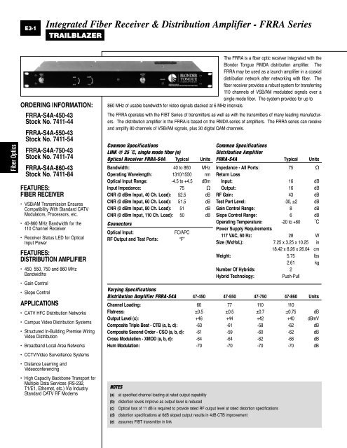
The FRRA is a fiber optic receiver integrated with the<br />
Blonder Tongue RMDA distribution amplifier. The<br />
FRRA may be used as a launch amplifier in a coaxial<br />
distribution network after networking with fiber. The<br />
fiber receiver provides a robust system for transferring<br />
110 channels of VSB/AM modulated signals over a<br />
single mode fiber. The system provides for up to<br />
860 MHz of usable bandwidth for video signals stacked at 6 MHz intervals.<br />
The FRRA operates with the FIBT Series of transmitters as well as with the transmitters of many leading manufacturers.<br />
The distribution amplifier in the FRRA is based on the RMDA series of amplifiers. The FRRA series can receive<br />
and amplify 80 channels of VSB/AM signals, plus 30 digital QAM channels.<br />
Common Specifications<br />
LINK @ 25 ˚C, single mode fiber (e)<br />
<strong>Optic</strong>al Receiver FRRA-S4A Typical Units<br />
Bandwidth: 40 to 860 MHz<br />
Operating Wavelength: 1310/1550 nm<br />
<strong>Optic</strong>al Input Range: -4.5 to +4.5 dBm<br />
Input Impedance: 75 Ω<br />
CNR (0 dBm Input, 40 Ch. Load): 52.5 dB<br />
CNR (0 dBm Input, 60 Ch. Load): 51.5 dB<br />
CNR (0 dBm Input, 80 Ch. Load): 51 dB<br />
CNR (0 dBm Input, 110 Ch. Load): 50 dB<br />
Connectors<br />
<strong>Optic</strong>al Input: FC/APC<br />
RF Output and Test Ports: “F”<br />
Common Specifications<br />
Distribution Amplifier<br />
FRRA-S4A Typical Units<br />
Impedance - All Ports:<br />
Return Loss<br />
75 Ω<br />
Input: 16 dB<br />
Output: 16 dB<br />
RF Gain: 43 dB<br />
Test Port Level: -30, ±2 dB<br />
Gain Control Range: 8 dB<br />
Slope Control Range: 6 dB<br />
Operating Temperature:<br />
Power Supply Requirements<br />
-20 to +60 ˚C<br />
117 VAC, 60 Hz: 28 W<br />
Size (WxHxL): 7.25 x 3.25 x 10.25 in<br />
18.42 x 8.26 x 26.04 cm<br />
Weight: 5.75 lbs<br />
2.61 kg<br />
Number Of Hybrids: 2<br />
Hybrid Technology: Push-Pull<br />
Varying Specifications<br />
Distribution Amplifier FRRA-S4A 47-450 47-550 47-750 47-860 Units<br />
Channel Loading: 60 77 110 110<br />
Flatness: ±0.5 ±0.5 ±0.7 ±0.75 dB<br />
Output Level (c): +46 +44 +42 +40 dBmV<br />
Composite Triple Beat - CTB (a, b, d): -63 -61 -58 -62 dB<br />
Composite Second Order - CSO (a, b, d): -61 -59 -60 -62 dB<br />
Cross Modulation - XMOD (a, b, d): -64 -64 -62 -66 dB<br />
Hum Modulation: -70 -70 -70 -70 dB<br />
NOTES<br />
(a) at specified channel loading at rated output capability<br />
(b) distortion levels improve as output level is reduced<br />
(c) <strong>Optic</strong>al loss of 11 dB is required to provide rated RF output level at rated distortion specifications<br />
(d) distortion specifications at 6dB sloped output results in 4dB CTB improvement<br />
(e) assumes FIBT transmitter in link