

Fiber Optic Design Guide - Maite y Mario
Fiber Optic Design Guide - Maite y Mario
Fiber Optic Design Guide - Maite y Mario

You also want an ePaper? Increase the reach of your titles
YUMPU automatically turns print PDFs into web optimized ePapers that Google loves.
LABORATORIES, INC.<br />
The Standard of Quality in TV Signal Distribution<br />
Multimode Broadband 5 Ch. <strong>Design</strong> Tool<br />
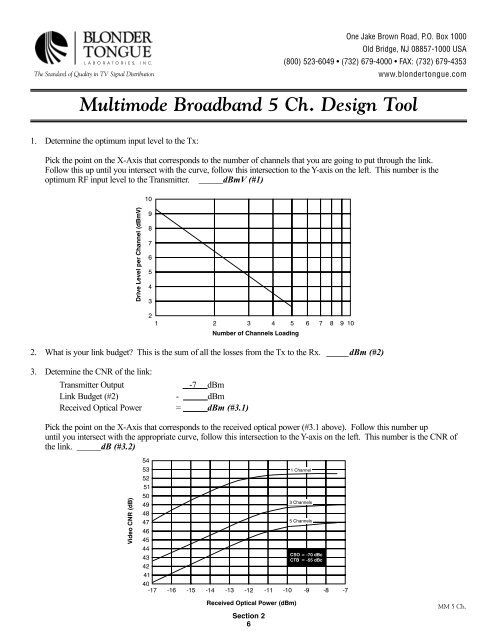
1. Determine the optimum input level to the Tx:<br />
Pick the point on the X-Axis that corresponds to the number of channels that you are going to put through the link.<br />
Follow this up until you intersect with the curve, follow this intersection to the Y-axis on the left. This number is the<br />
optimum RF input level to the Transmitter. ______dBmV (#1)<br />
2. What is your link budget? This is the sum of all the losses from the Tx to the Rx. _____dBm (#2)<br />
3. Determine the CNR of the link:<br />
Transmitter Output -7 dBm<br />
Link Budget (#2) - dBm<br />
Received <strong>Optic</strong>al Power = dBm (#3.1)<br />
Pick the point on the X-Axis that corresponds to the received optical power (#3.1 above). Follow this number up<br />
until you intersect with the appropriate curve, follow this intersection to the Y-axis on the left. This number is the CNR of<br />
the link. ______dB (#3.2)<br />
Section 2<br />
6<br />
One Jake Brown Road, P.O. Box 1000<br />
Old Bridge, NJ 08857-1000 USA<br />
(800) 523-6049 • (732) 679-4000 • FAX: (732) 679-4353<br />
www.blondertongue.com<br />
MM 5 Ch.