

Fiber Optic Design Guide - Maite y Mario
Fiber Optic Design Guide - Maite y Mario
Fiber Optic Design Guide - Maite y Mario

You also want an ePaper? Increase the reach of your titles
YUMPU automatically turns print PDFs into web optimized ePapers that Google loves.
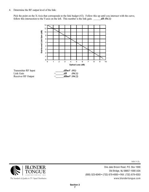
4. Determine the RF output level of the link:<br />
Pick the point on the X-Axis that corresponds to the link budget (#2). Follow this up until you intersect with the curve,<br />
follow this intersection to the Y-axis on the left. This number is the link gain. ______dB (#4.1)<br />
Transmitter RF Input ______dBmV (#1)<br />
Link Gain +______dB (#4.1)<br />
Receiver RF Output =______dBmV (#4.2)<br />
LABORATORIES, INC.<br />
The Standard of Quality in TV Signal Distribution<br />
Section 2<br />
7<br />
MM 5 Ch.<br />
One Jake Brown Road, P.O. Box 1000<br />
Old Bridge, NJ 08857-1000 USA<br />
(800) 523-6049 • (732) 679-4000 • FAX: (732) 679-4353<br />
www.blondertongue.com